Chapter 7 Selection guide of inverter Accessory IR610 high performance vector control frequency inverter user manual
- 158 -
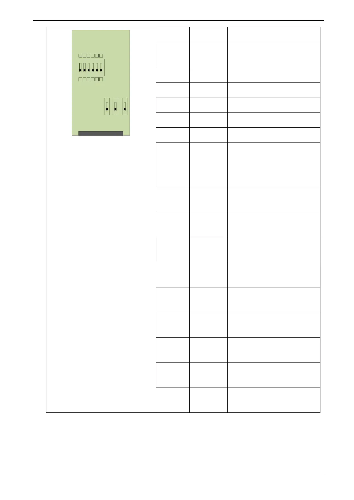
12VOC OC
5VTP TP
SW1
SW2
SW3
1
2
3
4
5
6
ON
0 0 0 0 0 0
1 1 1 1 1 1
J1
Power supply common terminal and
signal
Z signal crossover output (NPN
open collector type)
B-phase pulse frequency dividing
output (NPN open collector type)
Phase A pulse divider output
(NPN open collector type)
Z signal crossover output Z-
(differential output type)
Z signal crossover output Z+
(differential output type)
B-phase pulse divider output B-
(differential output type)
B-phase pulse divider output B+
(differential output type)
Phase A pulse divider output A-
(differential output type)
Phase A pulse divider output A+
(differential output type)
In the schematic diagram of the crossover card in Table 7-5, the dial switch indicates bit 0~bit5 of the frequency
division number from right to left, the frequency division range is 0~63, and the frequency division number is