VFD300A high performance vector control frequency inverter user manual Chapter 7 Selection guide of inverter Accessory
- 157-
12V OC OC
5V
TP TP
SW3
SW2
SW1
12V OC OC
5V
TP TP
SW3
SW2
SW1
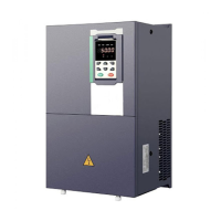
Chart 7-5 Collector open type, push-pull output type encoder DIP switch selection
When wiring, the /A, /B, /Z terminals of the PG card are not wired, and the signal output of the
encoder is connected to the A, B, and Z terminals of the PG card, as shown in the figure below.:
MT500-PG-INC1
VCC
0V
A
B
Z
PG
CARD
VCC
0V
A
B
Z
SHIELDING
CABLE
ENCODER
Chart 7-6 Collector open type, push-pull output type encoder wiring diagram
Differential output encoder wiring:
Select the encoder power supply through SW3 on the PG card, SW1 and SW2 to the TP side, as
shown below:
12V OC OC
5V
TP TP
SW3
SW2
SW1
12V OC OC
5V
TP TP
SW3
SW2
SW1
Chart 7-7 Differential output type encoder DIP switch selection
The wiring of the PG card and the encoder are connected one by one according to the silkscreen.
(2)Incremental encoder PG card with Frequency division
The input signal of the IR610-PG-INC2 crossover PG card can be differential or open collector type,
selected by the DIP switch; there are two sets of output signals, open collector type and
differential output type; The card's port definition is shown in the table below.
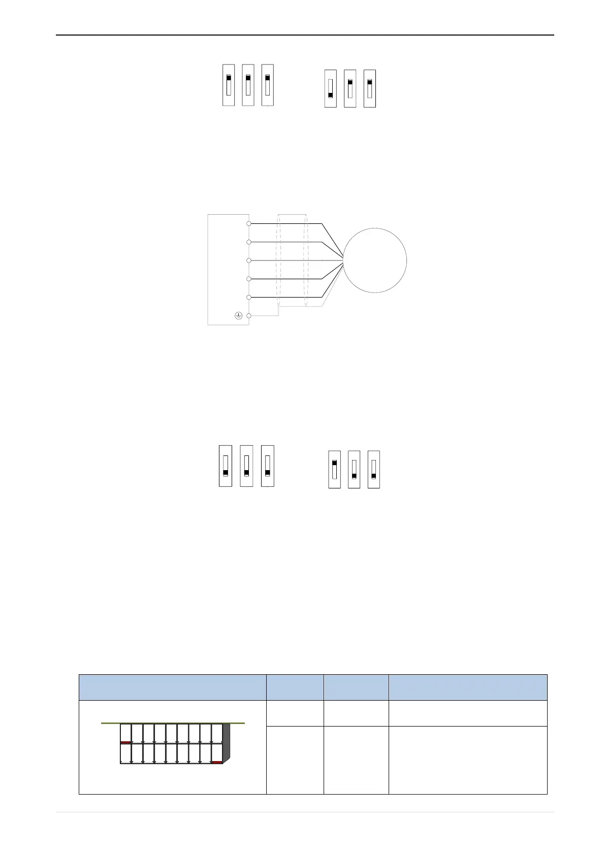
Chart 7-8 Incremental encoder PG card with frequency division (IR610-PG-INC2) port definition
181716151413121110
1 2 3 4 5 6 7 8 9
Power output for powering the
encoder
5V ± 2%, maximum 200mA