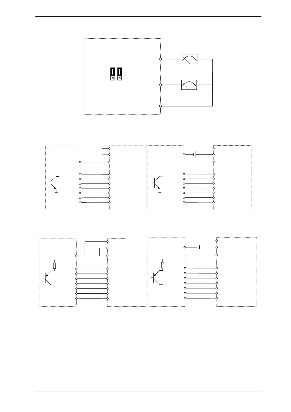
EasyManua.ls Logo

Vortex IR610 Series - Page 36

Vortex IR610 Series
179 pages
Print Icon
To Next Page IconTo Next Page
To Previous Page IconTo Previous Page
Loading...
Chapter3 product appearance and wiring IR610 high performance vector control frequency inverter user manual
- 32 -
IR610
AO1
AO2
GND
AO2
AO1
Jumper
switch
Voltage input
Current input
I
V
Figure 3-23 Analog output terminal wiring diagram
Digital input terminal instructions
IR610
External
controller
PLC
+24V
COM
NPN type
0V
0V
Y1Y7
DI1
DI2
DI3
DI4
HDI(DI5)
DI6
DI7
Y1
Y2
Y3
Y4
Y6
Y7
Y5
IR610
External
controller
PLC
+24V
COM
NPN type
0V
0V
Y1Y7
DI1
DI2
DI3
DI4
HDI(DI5)
DI6
DI7
Y1
Y2
Y3
Y4
Y6
Y7
Y5
+24V
NOTE(3)
ABy internal 24V with NPN mode BBy internal 24V with PNP mode
IR610
External
controller
PLC
+24V
COM
PNP Typt
VCC
Y1Y7
DI1
DI2
DI3
DI4
HDI(DI5)
DI6
DI7
Y1
Y2
Y3
Y4
Y6
Y7
Y5
VCC
IR610
External
controller
PLC
+24V
COM
PNP type
VCC
Y1Y7
DI1
DI2
DI3
DI4
HDI(DI5)
DI6
DI7
Y1
Y2
Y3
Y4
Y6
Y7
Y5
VCC
+24V
NOTE(3)
CNPN mode uses external +24V power supply DPNP mode uses external +24V power supply
3-24 Switching Digital input terminal wiring diagram
Note
When using external power supply to drive DI terminal , the shorting tab(connector slip) between +24V and
PLC must be removed, otherwise the product will be damaged!
When using an external power supply, connect the negative terminal of the external power supply to COM when sing
IR610