IR610 high performance vector control frequency inverter user manual Chapter3 Product appearance and wiring
- 33-
HDI, otherwise HDI is invalid!
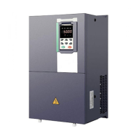
Switch output terminal instructions
The multi-function output terminals DO1 and HDO can be powered by the internal +24V power supply of the inverter
or an external power supply. The wiring diagram is as follows:
A、Use internal power supply B、Use external power supply
3-25 Switching digital output terminal wiring diagram
Note:
The multi-function terminal output is an open collector output with a maximum allowable current of 50mA. When
using the internal power supply, if the inductive load is driven, an absorption circuit such as an RC snubber circuit or
a freewheeling diode should be installed. When adding a freewheeling diode, be sure to confirm the polarity of the
diode, otherwise the product will be damaged. For external power supply, connect the negative terminal of the
external power supply to the COM terminal.
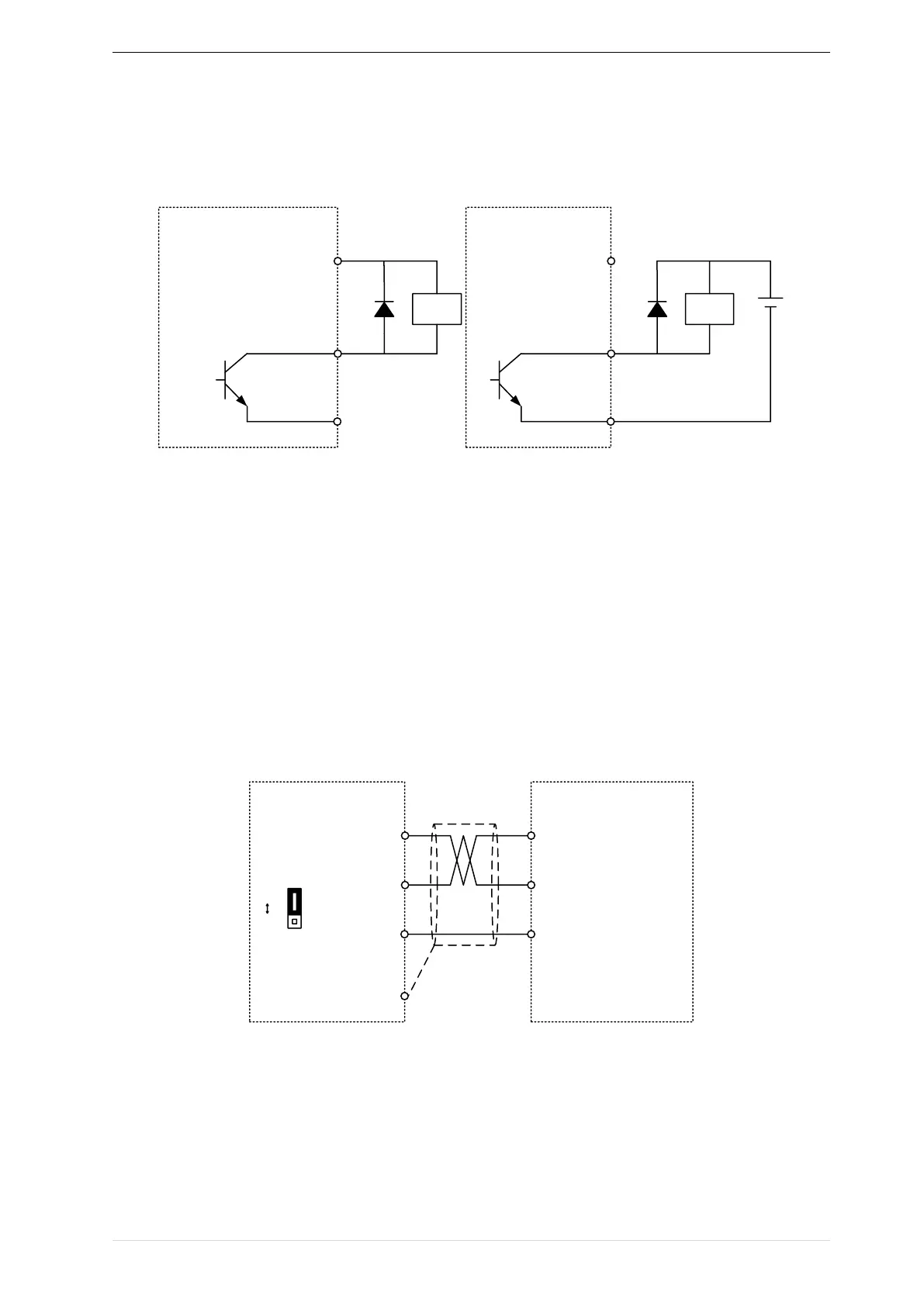
485Communication terminal instructions