By setting the speed factor and integration time of the speed regulator, you can adjust
Section vector controlled speed loop dynamic response characteristics. Increase the proportional gain and
reduce
The integration time can speed up the dynamic response of the speed loop, but the proportional gain is too large
Or the integration time is too small, it is easy to cause the system to oscillate, and the overshoot is too large.
Proportion increase
Too small is also likely to cause steady-state oscillations of the system, and there may be a speed difference.
PI has a close relationship with the inertia of the system. Adjust on the base of PI according to different loads to
meet various demands.
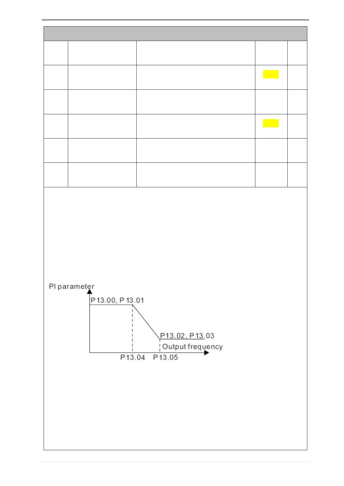
P13.00 and P13.01 are Speed adjuster parameter for low-speed use,scope of action from zero to P13.04
P13.02 and P13.03 are Speed adjuster parameter for high-speed use,scope of action from P13.05 to maximum
frequency


 To Next Page