30
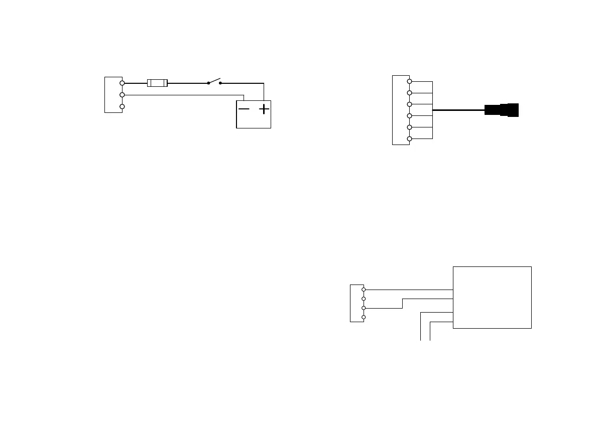
Meter power connection
Battery +
Battery -
NC
P3
1
2
3
Fuse 5A Ignition key
Use at least AWG 20 wires for the battery connection
to the Meter. Maximum allowed wire size is AWG16 for
the screw terminals. It is recommended that a 5A fuse
is used to protect wiring and Meter. The meter itself is
short circuit proof with internal current limitation at
5 - 6 A.
If the Meter is not connected to the ignition switch the
driver must turn off the Meter using its On/Off button to
reduce current consumption.
Smart box connection
Always use the prefabricated cable with molded
connector available from your dealer. There are cables
for connecting directly to a Smart box and for
connecting to a tractor to semi-trailer cable kit.
Not Connected
CAN L
CAN H
JBox detect
JBox power
JBox 0V
P7
1
2
3
4
5
6
Prefabricated
Meter to JBox cable
Printer connection
Read the printer instructions on connection details.
Below is a principal connection outlined but different
models may have different naming etc. Note that there
are some settings that must be done to adapt the
Meter to the printer.
Pin 4in connector P4 must not be connected.
TxD (out)
RxD (in)
0V
NC
P4
1
2
3
4
Printer
RD Recive Data (to printer)
SG Signal Ground
Power
Power ground
+ 0V
 Loading...