33373-001 Version A
resistive touch screen to provide system and patient information to the user and to allow the user to
modify ventilator settings. The Main System PCB handles all user interface requirements, including
updating the active matrix liquid crystal display (LCD), monitoring the membrane keypad, analog
resistive touch screen, and optical encoder for activity. The Main System PCB also performs all the
input/output functions of the UIM, including RS-232 (GSP and VOXP), printer, video output, and
IEEE 1073 Medical Information Bus (MIB).
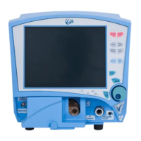
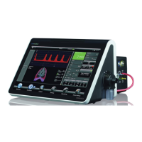
Liquid Crystal Display
The liquid crystal display (LCD) provides graphical and digital feedback to the clinician. The panel is
a 10.4” SVGA, 800x600 pixel, active matrix LCD. The LCD is used to implement the graphical user
interface (GUI). It provides all of the adjustable controls and alarms, as well as displays waveforms,
loops, digital monitors and alarm status in real time.
Touch Screen
The touch screen is a 10.4” analog resistive overlay on a piece of glass, which is placed over an
LCD screen. The touch screen and the LCD together provide a set of software configurable soft
keys. The software enables the keys to be context sensitive. The touch screen has a resolution of
1024x1024. Physically, the touch screen consists of two opposing transparent resistive layers
separated by insulating spacers. Touching the screen brings the two opposing layers into electrical
contact. The Y coordinate is determined by applying a voltage from top to bottom on the top
resistive layer. This creates a voltage gradient across this layer. The point of contact forms a
voltage divider, which is read by the analog-to-digital converter. The X coordinate is determined by
applying a voltage from left to right on the bottom resistive layer. Again this creates a voltage
gradient and the point of contact forms a divider, which is read with an analog-to-digital converter.
Membrane Panel
The membrane panel provides a set of permanent dedicated keys, which enable control of
ventilator functions. The membrane panel also provides visual display using embedded light
emitting diodes (LEDs). The membrane panel consists of membrane switches, which are read by
the microprocessor. The switches form a matrix of rows and columns. A key closure causes an
interrupt to the microprocessor, which responds by scanning the key matrix to determine which key
has been pressed.
Light Emitting Diodes (LED)
Some of the membrane keys require LED’s to indicate when the key is active. The LED’s are
embedded into the membrane panel.
Optical Encoder
The optical encoder is used to modify control settings. A setting is selected by pressing a soft key
on the touch screen and then modified by turning the optical encoder (data dial) to change the
value. When the encoder is rotated two pulse streams are generated, phase A and B. When the
encoder is turned clockwise, phase A leads B by 90 degrees. When the direction is counter
clockwise, phase B leads A by 90 degrees. The electronics uses the phase information to drive an
up-down counter, which is read by the microprocessor. The optical encoder is not interrupt-driven
and therefore must be polled by the microprocessor.
Back Light Inverter
The back light inverter converts 12 VDC into the high frequency AC voltage necessary to power the
LCD back light, which is used to illuminate the LCD.