33373-001 Version A
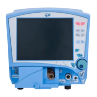
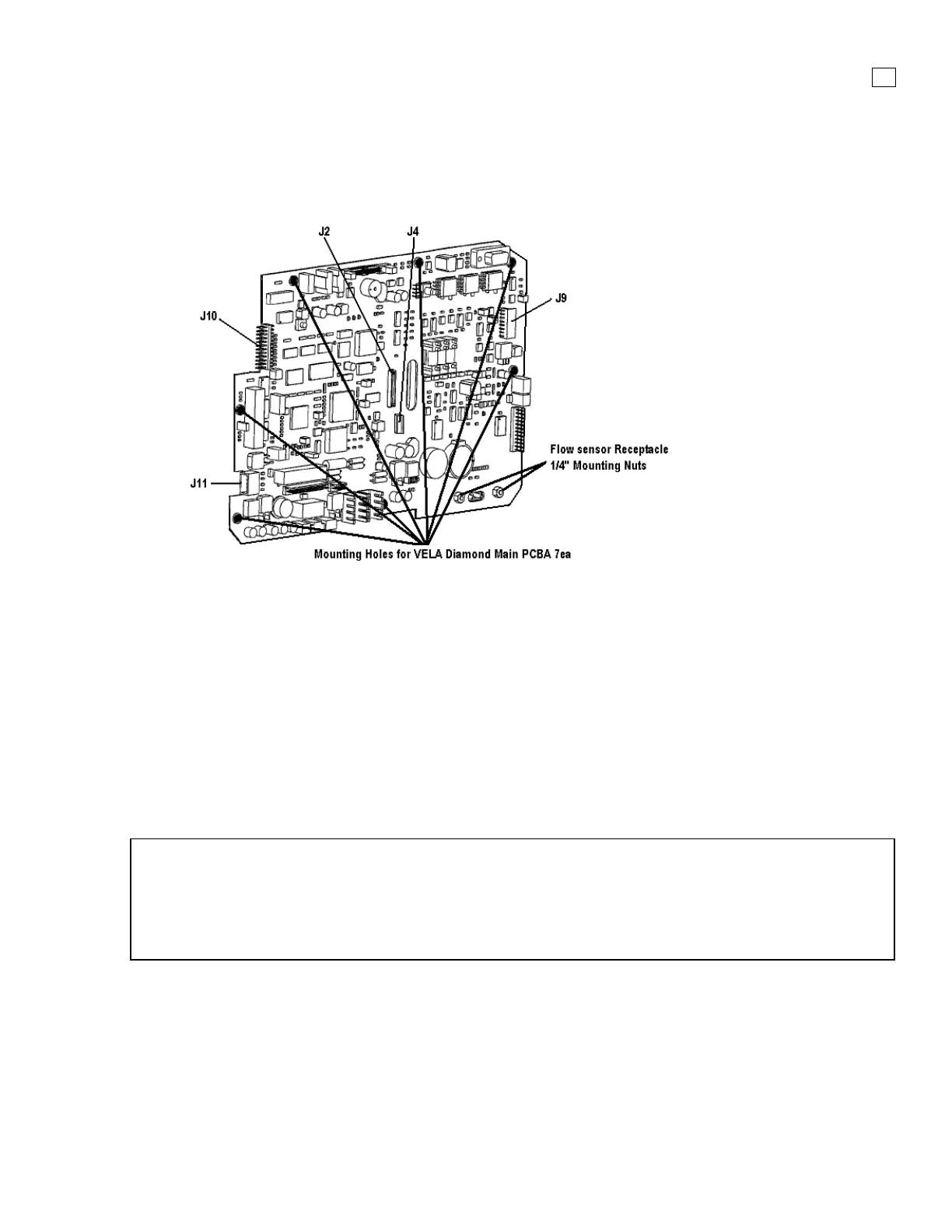
3.7 Main PCB
P/N 53420K (S/N AHT07499 a Below) / P/N 53420A (S/N AHT07500 and
Above)
Figure 3-8. Main PCB Assembly
Removal
After removal of the Front Panel Assembly, follow the steps below:
1. On the Main PCBA disconnect Soft key control panel flat cable at J10
2. On the Main PCBA disconnect Touch Screen flat cable at J9
3. On the Main PCBA disconnect the LCD 20 pin connecter at J2 (center of PCB)
4. On the Main PCBA disconnect the Backlight Inverter cable at J4 (center of PCB)
5. Remove the seven (7)mounting screws securing the Main PCBA to the LCD Panel
6. Remove the two (2) ¼” nuts securing the Flow Sensor Receptacle
7. Carefully lift the Main PCBA and disconnect the Optic Encoder cable at J11
NOTE
If you are not replacing the Main PCBA, and you have removed it to access other components do
not remove the Pneumatic tubing
If you are replacing the Main PCBA, carefully replace each tube one at a time to ensure proper
connection points
Installation
Install Main PCBA and follow removal process in reverse order
 Loading...