33373-001 Version A
Installation
Follow removal process in reverse order
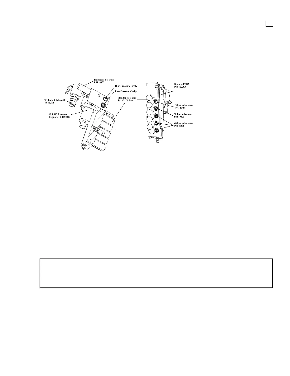
3.10 Blender Assembly
(P/N 16358A)
Figure 3-11. Blender Assembly
Removal
1. Remove the power cable, top cover, battery tray, and left panel.
2. If the rear panel is installed, remove the high and low pressure oxygen fittings from the rear
panel using a 3/4" wrench, noting that the high pressure fitting is located above the low pressure
fitting.
3. On the Blender PCBA disconnect the 12 wire connector at J301
4. Remove the bottom strip ambient air inlet filter by pinching and pulling it out
5. Remove (3) Phillips pan-head screws on the right side of the rear panel.
6. Use needle-nosed pliers to disconnect the oxygen diffuser tube as you remove the blender
assembly.
Installation
Follow removal process in reverse order
NOTE
When the blender is replaced or re-installed new screws will be required. These (3) screws, p/n
53002-56206, will be included with all blender assemblies. The screws can be ordered
separately.
 Loading...