33373-001 Version A
3.4 Right Panel Containing the Power PCB
(P/N 16351A)
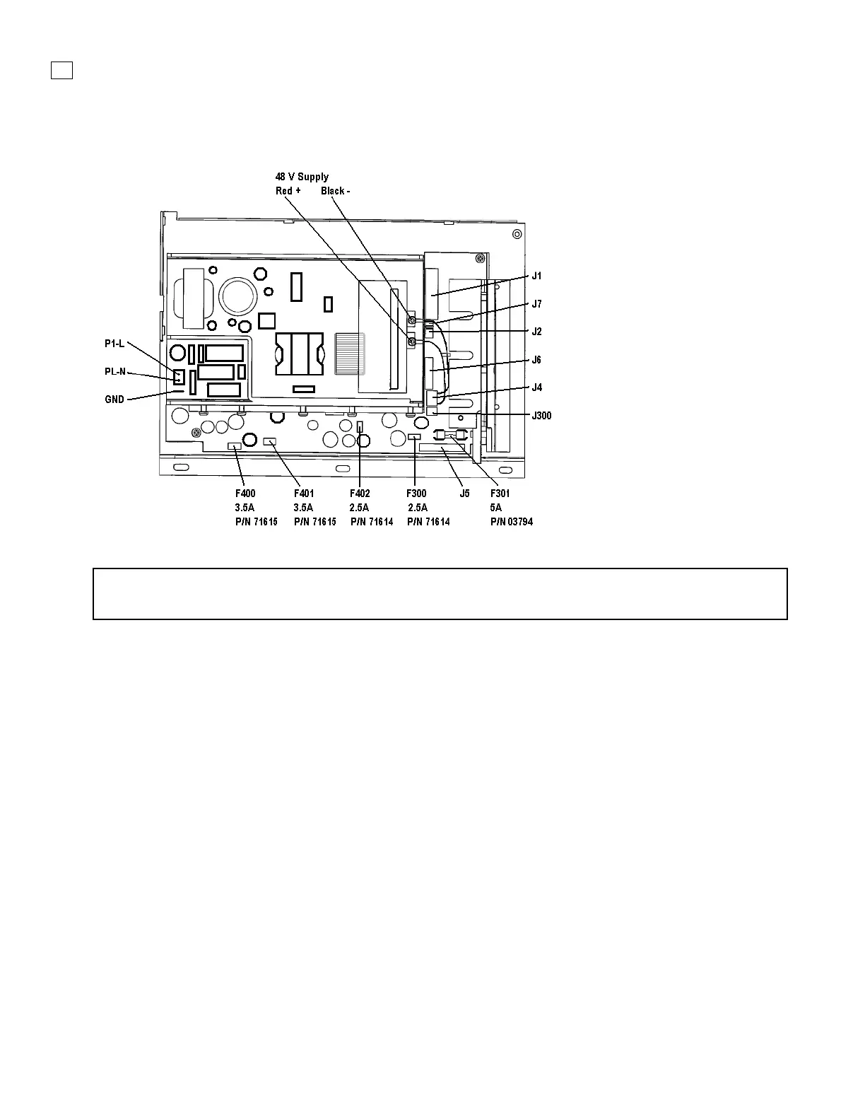
Figure 3-5. Power PCB Assembly
NOTE
The internal battery fuse is located on the power PCB. See F301 in Figure 3-5.
Removal
1. Remove the power cable, top cover, and battery tray.
2. Remove the (2) Phillips countersink screws from the right side of the rear panel.
3. Remove the (1) Phillips countersink screw in the upper front of the right panel.
4. Remove the (1) Phillips pan-head screw in the lower center of the right panel.
Gently lift out the panel and the power PCB. Lay the panel flat and make the following
disconnections:
5. On the Power PCBA disconnect the 26 pin ribbon cable at J1
6. On the Power PCBA disconnect the 2 wire (brown/black) connector at J7
7. On the Power PCBA disconnect the 3 wire connector at J2
8. On the Power PCBA disconnect the 10 wire connector at J6
9. On the Power PCBA disconnect the 2 wire (red/black) connector at J300
10. On the Power PCBA disconnect the 2 wire (black/white) connector at P1-L & P1-N
11. On the Power PCBA disconnect the ground wire (green/yellow) spade connector
 Loading...