3 Diagnostics, Troubleshooting and Testing
22
WABCO Maintenance Manual MM-0112 (Revised 07-18)
Blink Code Conditions
When using blink code diagnostics, the following conditions could
occur:
Table B: Blink Code Conditions
Blink Code Identification
Use the following information to identify the blink code:
Condition Reason Action
ABS indicator lamp does not
come on at ignition.
Loose or burned-out bulb. Check bulb.
Check connections.
Make necessary repairs.
Voltage not within acceptable range
(9.5-14.0 volts) (18-32 for 24V
system).
Check connections.
Measure voltage.
Make necessary repairs.
Can’t use blink code
diagnostics. ABS indicator
lamp will not go off when
blink code is activated.
Switch not held for correct length of
time:
1 Second — Diagnostics Mode
3 Seconds — Clear All Mode
Repeat procedure, hold switch for correct length of time.
Incorrect or faulty wiring. Inspect and repair wiring.
Fault not erased from ECU after report. Repeat procedure until System O.K. code received.
Eight flashes not received
after blink code switch
pressed for at least three
seconds, then released.
Active faults still exist. Identify active faults, then make necessary repairs.
Turn ignition OFF, then repeat Blink Code Diagnostics.
First Digit (Type of Fault) Second Digit — Specific Location of Fault
1 No faults 1 No faults
2 ABS modulator valve
3 Too much sensor gap
4 Sensor short or open
5 Sensor signal erratic/tire size
6 Tooth wheel
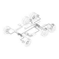
1 Right front steer axle (curb side)
2 Left front steer axle (driver’s side)
3 Right rear drive axle (curb side)
4 Left rear drive axle (driver’s side)
5 Right rear/additional axle (curb side)
6 Left rear/additional axle (driver’s side)