3 Diagnostics, Troubleshooting and Testing
33
WABCO Maintenance Manual MM-0112 (Revised 07-18)
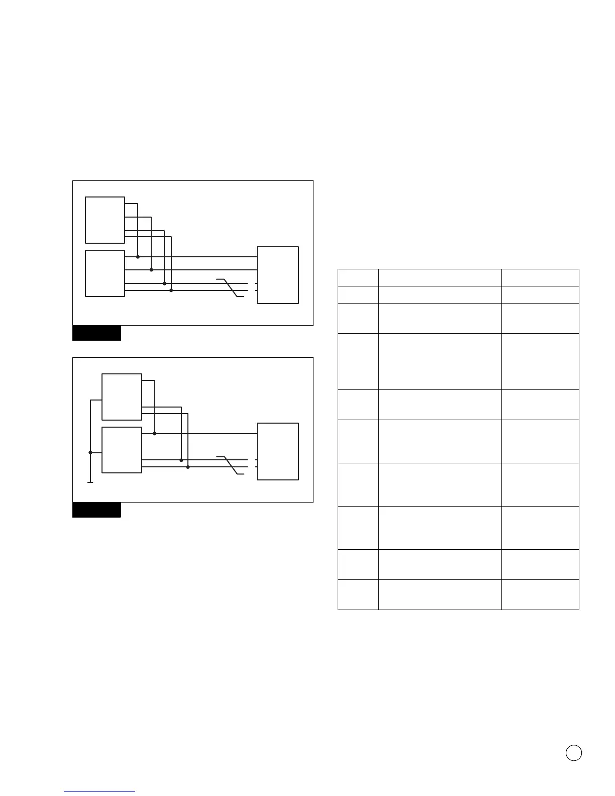
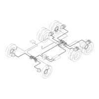
ESC CAN Network Testing
The ECU, SAS and ESC module are all connected on propriety CAN
network with internal terminating resistors on each one of these
components. A failure to one of the components will cause others to
fault out. Figure 3.32 and Figure 3.33.
Figure 3.32
Figure 3.33
ESC Module Testing
Electrical Checks
For the following checks, all of the ECU connectors must be plugged
in as well as the SAS. The ECU provides voltage, ground and CAN
communication to ESC module.
앫 Take measurements at the ESC module harness connector.
Figure 3.34 and Figure 3.35.
앫 Measure voltage supply Key ON.
앫 Measure CAN High voltage Key ON.
앫 Measure CAN Low voltage Key ON.
앫 Measure terminating resistance across CAN High and Low with
Key OFF.
앫 Frame-mounted ECU only: Measure ground resistance Key OFF
to chassis ground.
With ECU and ESC Module disconnected:
앫 Verify continuity end to end on each line
앫 Verify no shorts to ground or battery on all lines.
앫 Verify no continuity between pins.
Measurements should read as follows:
NOTE: Do not load test across power and ground at the ESC
Module.
Figure 3.32
Figure 3.33
4010627a
SAS
ESC
MODULE
CAB
ECU
CAN
L
H
GND
U
B
4010628a
SAS
ESC
MODULE
FRAME
ECU
CAN
L
H
GND
U
B
Pins Circuit Measurement
1 Voltage Supply to Chassis Ground 8.0-16.0V
2 (Frame-mounted only) ESC
Ground to Chassis Ground
Less than 1 ohm
resistance
2 (Cab-mounted only) ESC Ground
to Chassis Ground
Should have
continuity but will
not be less than 1
ohm
3 and 4 Terminating Resistance between
ESC CAN-High to ESC CAN-Low
Approximately 90
ohms
1 With ECU disconnected, check
power supply for battery voltage
or ground.
No continuity
2 With ECU disconnected, check
ground for battery voltage or
ground.
No continuity
3 and 4 With ECU disconnected, check
CAN lines for battery voltage or
ground.
No continuity
3 CAN High Voltage to Chassis
Ground
2.5-5.0V
4 CAN Low Voltage to Chassis
Ground
0.1-2.4V