wc_tx003764gb.fm
64
Schematics HI 110 / 200 / 300
10 Schematics
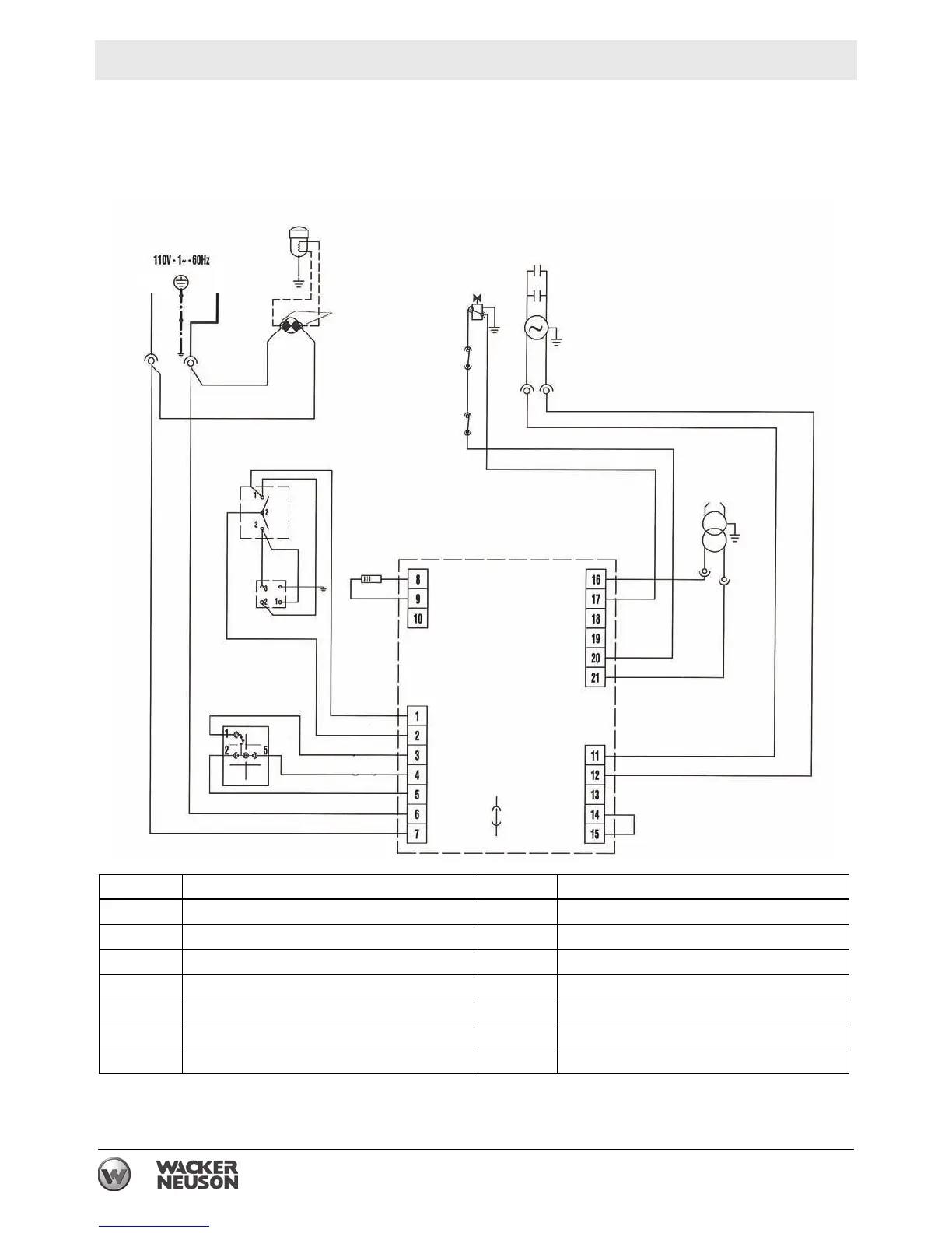
10.1 Electrical Schematic - HI 110 D, HI 110 HDD
12
3
7
6
5
2
7
11
8
9
13
4
J4
J3
10
1
J1
J2
14
BK
BK
BK
BK
BK
BK
BK
RD
RD
RD
RD
RD
YL
BU
GY
WH
WH
WH
WH
WH
WH
WH
RD
TGRD91 CSA 120V
LN
wc_gr012018
No. Description No. Description
1 Fuse 8 Control switch
2 Overheat thermostat 9 Room thermostat plug
3 Solenoid valve 10 Control box
4 CAD cell 11 Air pressure switch
5 Capacitor 12 Heated fuel filter (optional)
6 Fan motor 13 Reset switch/lockout indicator
7 Electric pilot lamp 14 High voltage transformer
 Loading...