15
VM 500
VM 500
B_03418
3
4
1
2
OPERATING MANUAL
EDITION 03/2012 PART NUMBER DOC 2318724
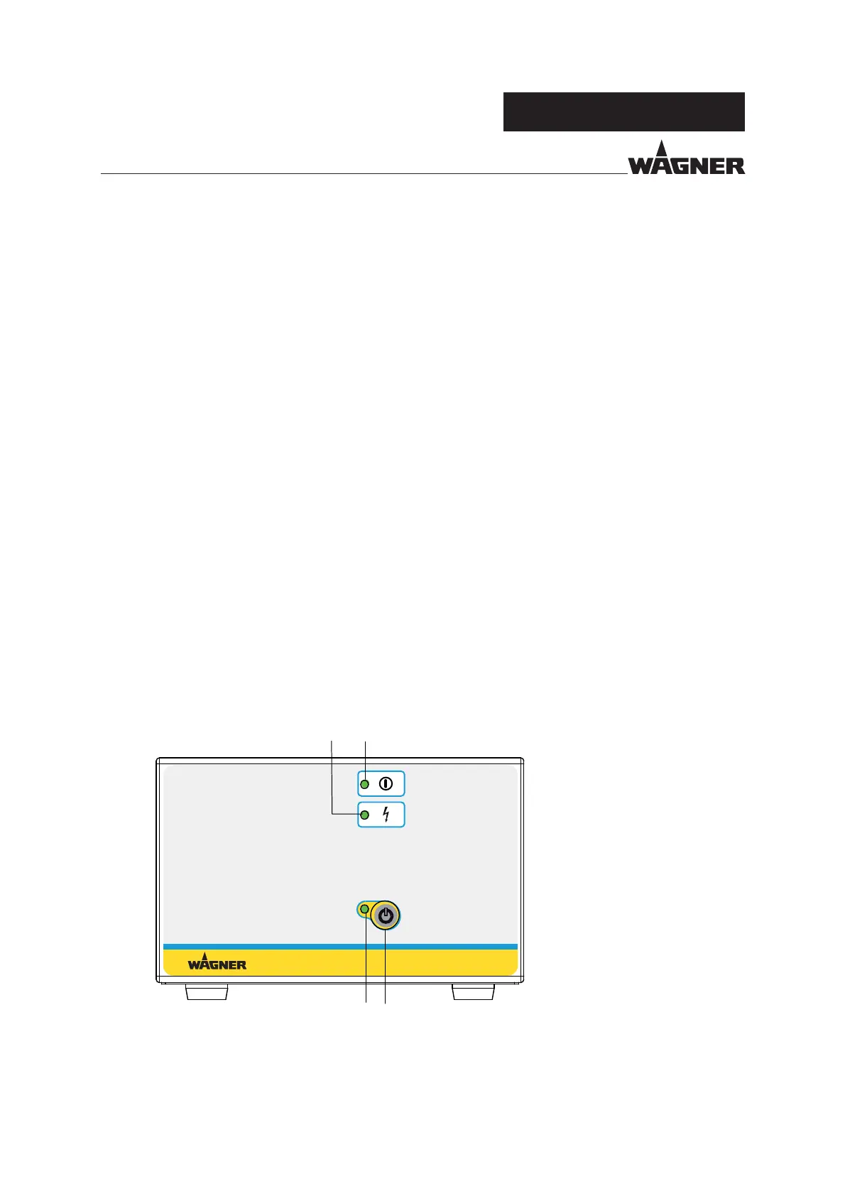
1 Illuminated display: High-voltage
2 Illuminated display: Operating signal
3 Push button: Standby mode
4 Illuminated display: Standby
4.4 FUNCTIONAL DESCRIPTION
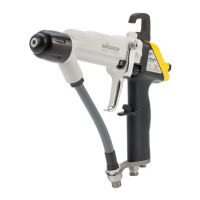
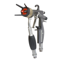
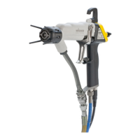
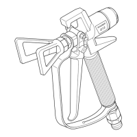
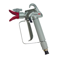
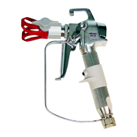
The VM 500 control unit together with the suitable GM 5000EA or GM 5000EAC spray gun
and other components form an electro-static hand spray system. The VM 500 supplies the
control voltage for the spray gun, in which high-voltage is subsequently produced. The
high-voltage supply is switched on and off with the trigger of the spray gun.
The special linear characteristic for high-voltage ensures that if the spray gun is brought
too close to the workpiece (or to earth) the high-voltage is reduced automatically to
prevent an accidental spark discharge.
The VM 500 also offers a fault display.
4.5 OPERATING ELEMENTS AND CONNECTIONS
4.5.1 OPERATING ELEMENTS FRONT SIDE