Do you have a question about the Walker Edison BQSPIN and is the answer not in the manual?
Ensure parts availability, use correct tools, and avoid power tools for safe assembly.
Follow steps carefully and utilize two people for easier assembly.
Understand the types of hardware used: wood dowels, screws, and bolts.
Insert wood dowels (E) into parts 5, 28, 29 and wood dowels (F) into part 13.
Attach center bar support (R) into parts 28, 29 with screw (P) using a Phillips head screwdriver.
Attach middle foot support (23) to cross bar (24) with screw (A) using the hex key (J).
Connect parts 20, 21 to parts 28, 29.
Secure parts 20, 21 to parts 28, 29 with screws (A), using the hex key (J).
Connect parts 28, 29 to parts 20, 21 with screw (B), using a Phillips head screwdriver.
Attach feet (15) to side rails using screws (M, D) and union screws (N) with hex key (J).
Secure feet (15) to side rails with screw (B) using a Phillips head screwdriver.
Attach metal connector plates (Q) to the corners of the bed with screws (P).
Secure part (24) to center bar support (R) with screw (P) using a Phillips head screwdriver.
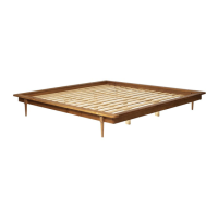
Place slats (2) onto frame parts and secure with screw (B), using spacing part (L).
Connect parts (5) to part (7) with screw (B) using a Phillips head screwdriver.
Attach parts (13) to part (6) with bolt (D) using a hex key (J).
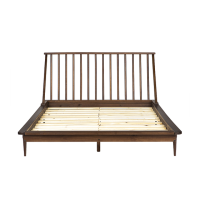
Fit headboard spindle (13) into part (5) and secure with bolt (D) using hex key (J).
Insert spindle (1) and screw (B) to connect to part (6) using a Phillips head screwdriver.
Insert headboard slat (14) on part (7), with screws (P), using a Phillips head screwdriver.
Insert screws (B) in the spindles (1) using a Phillips head screwdriver.
Insert Wood Dowel (E) into part (14).
Align dowels in part (7) with dowel holes in part (29) and press together firmly.
Join part (7) to parts (29) and (5) with screw (M) and union screw (N) using hex key (J).
Final check and confirmation of assembly.
| Brand | Walker Edison |
|---|---|
| Model | BQSPIN |
| Category | Indoor Furnishing |
| Language | English |