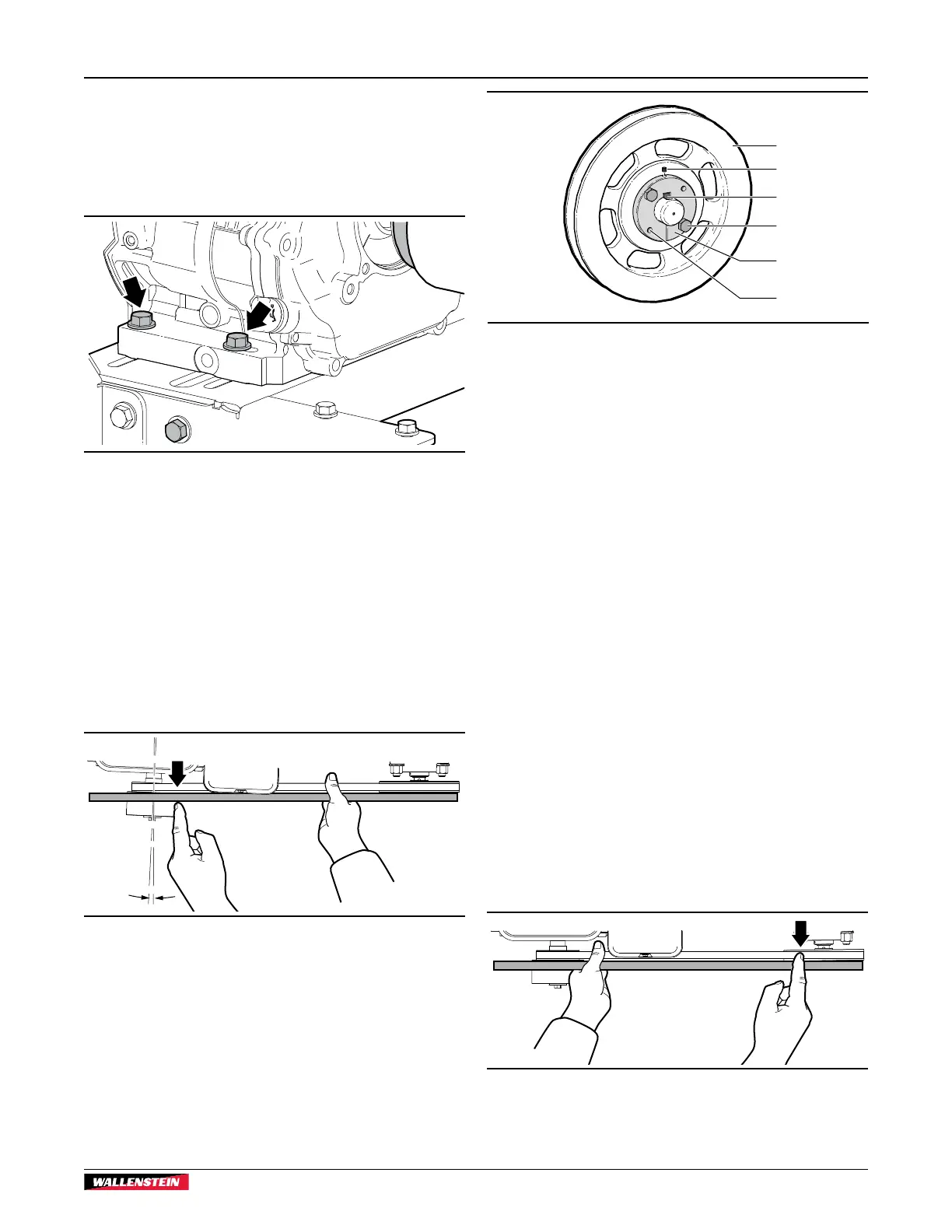
9.6.3 Align the Engine Mount
After changing the drive belt or loosening the engine mounts, the
drive belt may become misaligned.
1. Loosen the four engine mount bolts. If one corner of the
engine mount does not need to move, leave the bolt snug.
Fig. 28 – Engine mount bolts (two of four)
2. Turn the engine to one side or the other on the base to
adjust its position.
3. Use a straight edge to check the drive-belt and sheave
alignment (Fig. 29).
4. For the best results, repeat step 3.
5. Use a calibrated torque wrench to tighten the four engine
mount bolts to 33 lbf•ft (45 N•m).
6. Check the drive-belt tension. If required, set the tension.
7. Install the drive-belt guard.
01947
Fig. 29 – Engine mount alignment
9.6.4 Align the Rotor Sheave
If the rotor sheave loosens on the shaft, it can become
misaligned with the engine clutch and result in poor belt
alignment.
1
2
3
4
5
6
01096
Fig. 30 – Rotor sheave
1. Sheave
2. Set screw
3. Shaft key
4. Sheave bolts
5. Sheave hub
6. Threaded puller holes
1. Remove the drive belt.
2. Remove the set screw from the sheave (2).
3. Remove the sheave bolts (4), and then thread them into the
puller holes on the sheave hub (5).
4. Slightly separate the hub and the sheave, so that they can
move on the shaft. Turn in both bolts evenly in 1/4-turn
increments.
5. Lightly tap the sheave hub with a block of wood to move
it in or out on the shaft until it aligns with engine clutch
sheave.
6. Place a straight edge along the face of the engine clutch
and rotor sheave to make sure that they are aligned.
7. After the rotor sheave is aligned, insert the hub bolts and
snug them up to the sheave. Repeat step 6 to check the
alignment.
8. Tighten the hub bolts evenly in 1/4-turn increments until
they are firmly seated.
9. Install and tighten the set screw. Repeat step 6 to check the
alignment.
10. Check the drive-belt tension. If required, set the tension.
11. Install the drive-belt guard.
01948
Fig. 31 – Rotor sheave alignment
BXMT3213
Trailer Chipper / Shredder
Service and Maintenance
41