5.0 INSTALLATION AND FIXING
VL
2
VAL.130.--.M.EN Issue: A1
09.16
25
5.6 Assembly instruction
SUPPLY:
Manual Actuator assembly
A) 1 hand wheel cpl. with spindle
B) 1 nut screw
%ROWVQXWVZDVKHUV
&DUGERDUGER[
NOTE: During assembly the blade must rest on all bearings. Only after, lay the valve on the lower side for
actuator assembly.
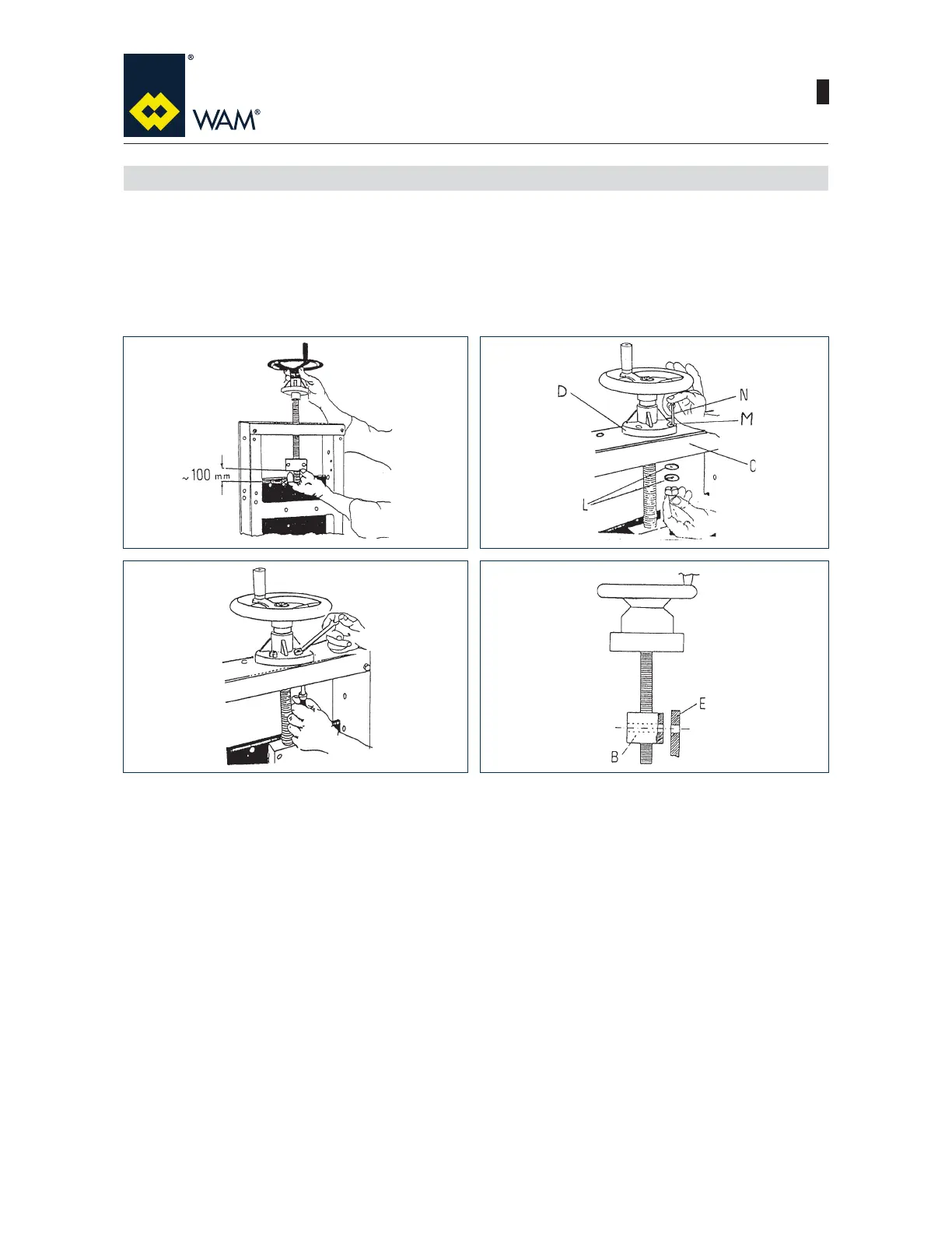
1) lnsert spindle (A) into the central bore on the upper crosspiece of valve body. Screw the nut screw (B) onto
the pindle (A) by approx. 100 mm.
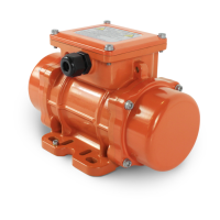
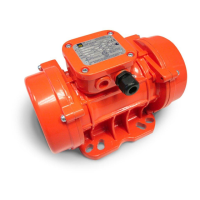
2) lnsert the larger washers (L) on the inside of the valve frame (C) from below and the smaller washers (M)
on the hand wheel support (D). lnsert the bolts and nuts (N).
3) Tighten the bolts and nuts.
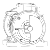
4) Rotate the hand wheel to match the bores on nut screw (B) and on blade (E).