5.0 INSTALLATION AND FIXING
VL
2
VAL.130.--.M.EN Issue: A1
09.16
32
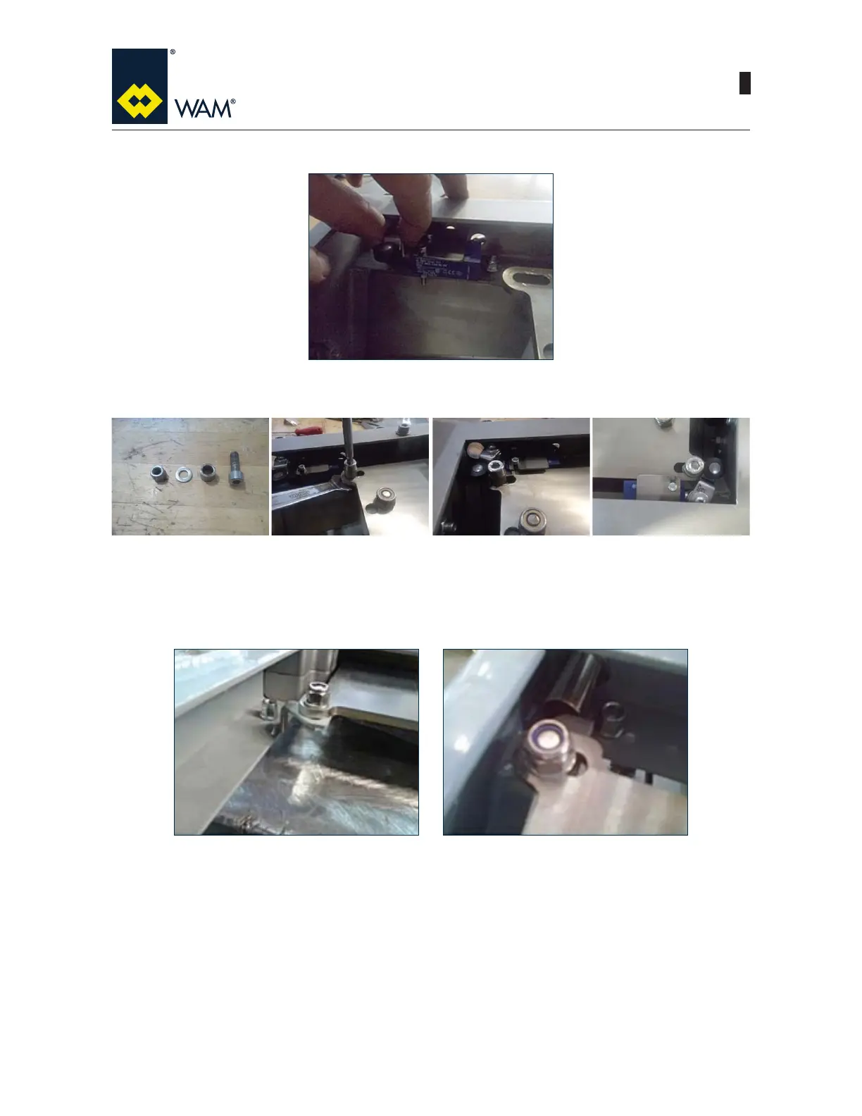
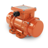
4) Fix the plate on the outside of the valve body by means of the two screws M6x16 and washers.
5) Fit the drive system on the blade of the limit switch (cam) with the screw M8x25, screw, washer and spacer
DVVKRZQLQWKH¿JXUH&KHFNWKHRSHUDWLRQWKHSULRUWRVWDUWLQJUHJXODURSHUDWLRQ
6) Repeat the operation for the second limit switch, if required.
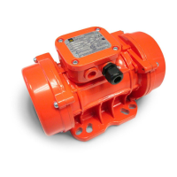
INDUCTIVE LIMIT SWITCH
1)5HPRYHIURPWKHER[WKHGHWHFWLRQV\VWHPFRQVLVWVRISODWHDQGWKHUHODWHG¿[LQJVFUHZV7KHQDVVHPEO\
according to the indications.