Watson-Marlow 620DuN and 620Du User Manual 75
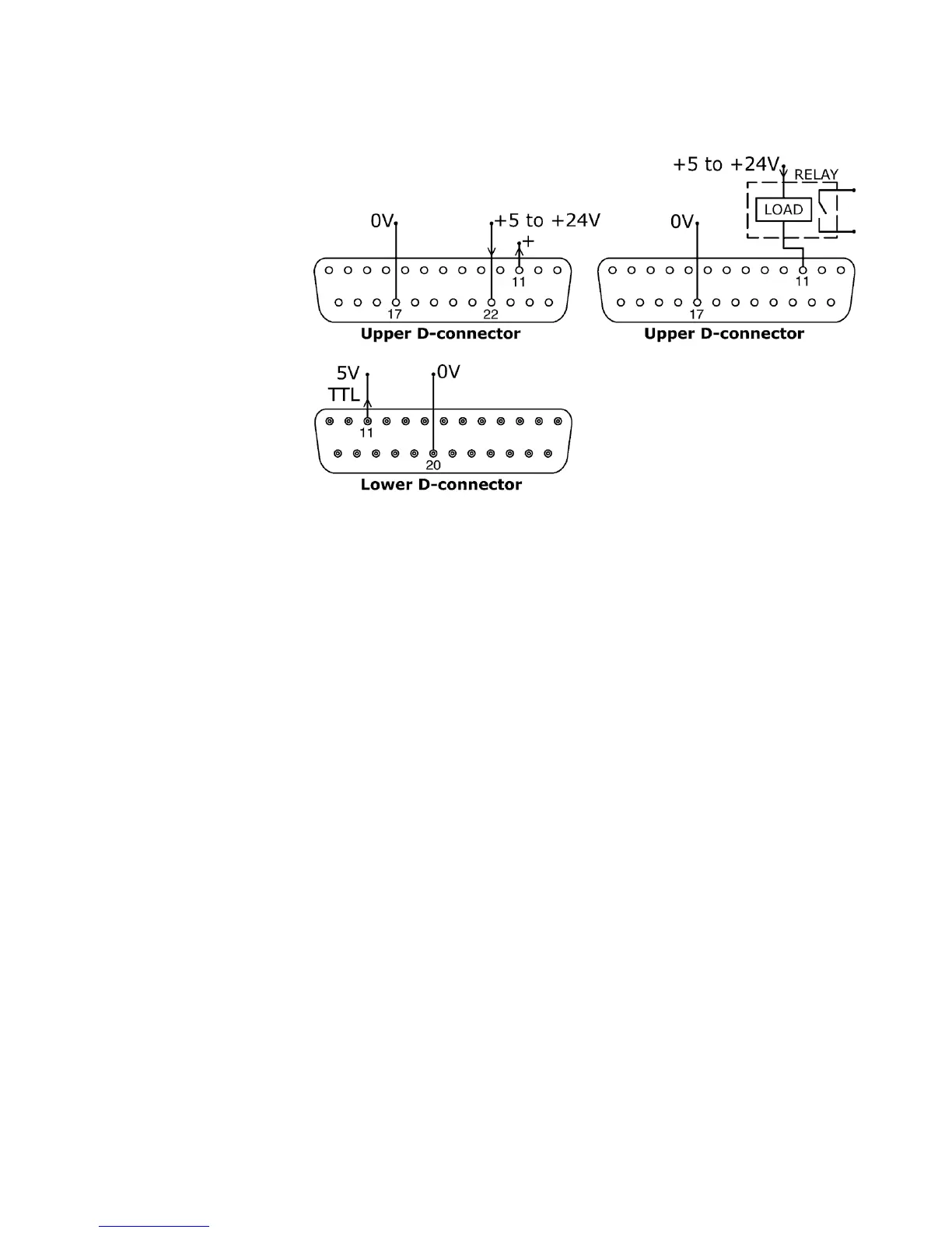
23.10.2 Logic output 2
Output 2 is taken from pin 11 of the upper D-connector, depending on the logic state
of the function assigned to Output 2. Alternatively, a load such as a relay coil may
be connected to pin 11, ground to pin 17. Current will flow through the circuit
depending on the logic state of the function assigned to Output 2. Do not connect
to any device requiring more than 50mA.
Additionally, output 2 is available as a 5V TTL logic signal on pin 11 of the lower D-
connector. It will change state corresponding to the logic state of the function
assigned to Output 2. Do not connect to any device requiring more than 1 TTL load.
By default, output 2 is configured to indicate Direction status. See 12 Switching the
pump on for the first time.