24 25
For a correct installation, refer to dedicated user guides of each product, then:
WIRING CONNECTION:
• Connect each receiver (BT-FR02 RF, BT-PR02 RF and/or BT-WR02 RF)
to related electrical device
VIRTUAL – RF CONNECTION:
• Create the virtual rooms in the Central Unit BT-CT02 RF
1 Pair each thermostat as a Heating device in each virtual room in the
Central Unit BT-CT02 RF
2-3-4 Pair each receiver in each virtual room of the Central Unit BT-CT02 RF
as a Heating device and select electrical heating mode in the Heating
Parameter
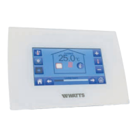
BT-CT02 RF
BT-D02 RF
3.3 Electrical heating System
3.3.1 One (or several) electrical heaters in multi zones with
centralized remote control.
Equipments:
• 1 (or more) Thermostat BT-D02 RF (or BT-A02 RF or BT-DP02 RF)
• Several receivers : BT-FR02 RF, BT-PR02 RF or BT-WR02 RF
• 1 Central Unit BT-CT02 RF
27
For a correct installation, refer to dedicated user guides of each product, then:
WIRING CONNECTION:
• Connect each receiver (BT-FR02 RF, BT-PR02 RF and/or BT-WR02 RF) to related electrical
device
VIRTUAL – RF CONNECTION:
• create the virtual rooms In the Central Unit BT-CT02 RF
1 Pair each thermostat as a Heating device in each virtual room in the Central Unit
BT-CT02 RF
2-3-4 Pair each receiver in each virtual room of the Central Unit BT-CT02 RF as a Heating
device and select electrical heating mode in the Heating Parameter
BT-WR02 HC RF
BT-PR02 RF
BT-FR02 RF
BT-WR02 HC RF

 Loading...