14 15
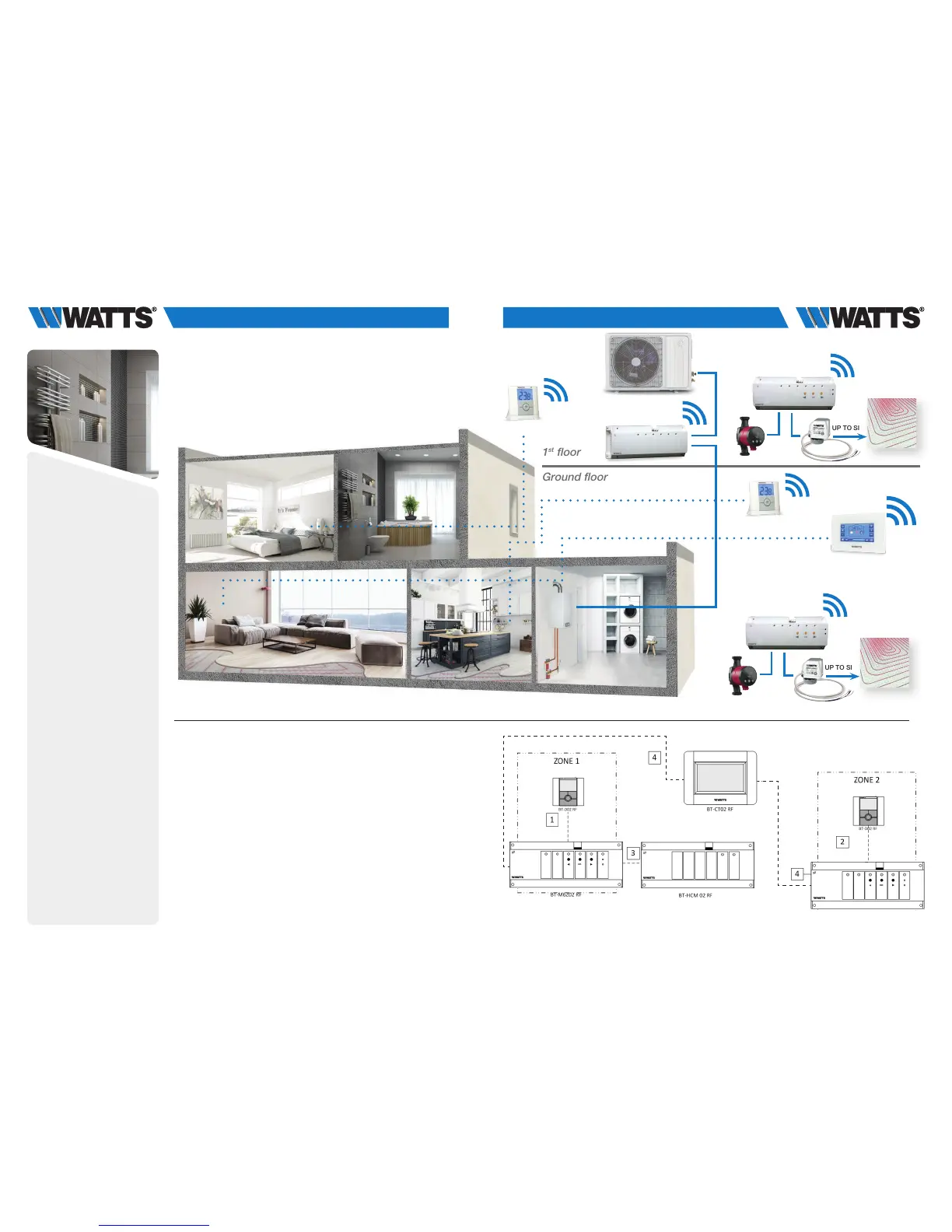
3.1.5 Water floor heating and cooling (multi zones).
Equipments:
• 2 Connecting boxes BT-M6Z02 RF
• 2 (or more) Thermostats BT-D02 RF (or BT-A02 RF, BT-DP02 RF,
BT-D02 RH RF) **
• 1 Connecting box BT-HCM02 RF to drive the heating or cooling mode
• 1 Central Unit BT-CT02 RF
For a correct installation, refer to dedicated user guides of each product, then:
WIRING CONNECTION:
• Connect the actuators (eg. 22C – 22CX series) to the connecting box BT-M6Z02 RF
• Connect the circulating pumps to the related connecting box BT-M6Z02 RF (*)
•
Connect the Hot/Cool Module to the load (eg. A/C system) and to the heating relay
of the boiler
VIRTUAL – RF CONNECTION:
1-2 Pair each thermostat to each zone of the BT-M6Z02 RF.
One thermostat can drive several zones.
3 Pair the BT-HCM02 RF to the BT-M6Z02 RF.
Note – Only one Hot/Cool module BT-HCM02 RF per System (**).
4 Pair in master mode each BT-M6Z02 RF to the Central Unit BT-CT02 RF.
Name the virtual rooms in the BT-CT02 RF and select the hydraulic circuit.
1
st
floor
Ground floor
**) In application with humidity drier (for system limitation ref. to pag. 33) connect it to the output of Hot/Cool
module for triggering it on/off and managing relative humidity (%). In this case it is necessary to install at
least 1 thermostat BT-D02 RF with Humidity Sensor and locate it in a central area of the installation.
* ) In this application each BT-M6Z02 RF is connected to a circulating pump. DIP SWITCH #1 Configuration:
OFF = LOCAL. In case of an installation with more than one BT-M6Z02 RF connecting box and only 1
circulating pump, DIP SWITCH #1 Configuration: ON = GLOBAL on the BT-M6Z02 RF that drives the
circulating pump (= BT-M6Z02 Master).
17
WIRING CONNECTION:
• Connect the actuators (eg. 22C – 22CX series) to the connecting box BT-M6Z02 RF
• Connect the circulating pumps to the related connecting box BT-M6Z02 RF (*)
• Connect the Hot/Cool Module to the load (eg. A/C system) and to the heating relay
boiler
VIRTUAL – RF CONNECTION:
1-2 Pair each thermostat to each zone of the BT-M6Z02 RF. One thermostat can drive
several zones.
3 Pair the BT-HCM02 RF to the BT-M6Z02 RF.
NOTE – Only one Hot/Cool module BT-HCM02 RF per System (**).
4 Pair in master mode each BT-M6Z02 RF to the Central Unit BT-CT02 RF.
Name the virtual rooms in the BT-CT02 RF and select the hydraulic circuit.
* In this application each BT-M6Z02 RF is
connected to a circulating pump.
DIP SWITCH #1 Configuration: OFF = LOCAL.
In case of an installation with more than one
BT-M6Z02 RF connecting box and only 1
circulating pump,
DIP SWITCH #1 Configuration: ON = GLOBAL
M6Z02 RF that drives the circulating
pump (= BT-M6Z02 Master).
** In application with humidity drier (for system limitation ref. to pag. 34) connect it to the output of Hot/Cool module for
triggering it on/off and managing relative humidity (%). In this case it is necessary to install at least 1 thermostat BT-D02 RF
with Humidity Sensor and locate it in a central area of the installation.
17
WIRING CONNECTION:
• Connect the actuators (eg. 22C – 22CX series) to the connecting box BT-M6Z02 RF
• Connect the circulating pumps to the related connecting box BT-M6Z02 RF (*)
• Connect the Hot/Cool Module to the load (eg. A/C system) and to the heating relay
boiler
VIRTUAL – RF CONNECTION:
1-2 Pair each thermostat to each zone of the BT-M6Z02 RF. One thermostat can drive
several zones.
3 Pair the BT-HCM02 RF to the BT-M6Z02 RF.
NOTE – Only one Hot/Cool module BT-HCM02 RF per System (**).
4 Pair in master mode each BT-M6Z02 RF to the Central Unit BT-CT02 RF.
Name the virtual rooms in the BT-CT02 RF and select the hydraulic circuit.
* In this application each BT-M6Z02 RF is
connected to a circulating pump.
DIP SWITCH #1 Configuration: OFF = LOCAL.
In case of an installation with more than one
BT-M6Z02 RF connecting box and only 1
circulating pump,
DIP SWITCH #1 Configuration: ON = GLOBAL
on the BT-M6Z02 RF that drives the circulating
pump (= BT-M6Z02 Master).
** In application with humidity drier (for system limitation ref. to pag. 34) connect it to the output of Hot/Cool module for
triggering it on/off and managing relative humidity (%). In this case it is necessary to install at least 1 thermostat BT-D02 RF
with Humidity Sensor and locate it in a central area of the installation.
BT-D02 RF
BT-D02 RF
UP TO SIX
BT-M6Z02 RF
BT-HCM02 RT
BT-CT02 RF
BT-M6Z02 RF
UP TO SIX
BT-M6Z02 RF