12 13
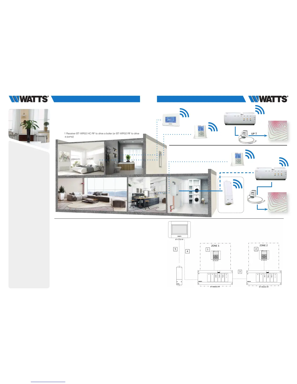
3.1.4 Water floor heating (multi zones) with several BT-M6Z02 RF
and pump management.
Equipments:
• 2 Connecting Boxes BT-M6Z02 RF
• 2 (or more) Thermostats BT-D02 RF (or BT-A02 RF, or BT-DP02 RF)
• 1 Central Unit BT-CT02 RF
• OPTION – If necessary = in case manifold is too far from boiler:
1 Receiver BT-WR02 HC RF to drive a boiler (or BT-WR02 RF to drive
a pump)
For a correct installation, refer to dedicated user guides of each product, then:
WIRING CONNECTION:
• Connect the actuators (eg. 22C – 22CX series) to the connecting box BT-M6Z02 RF
• Connect the connecting box BT-M6Z02 RF (ZONE 1 ) to the heating relay of boiler
or
• OPTION – if not possible (eg. the manifold is too far) connect a Receiver
BT-WR02 HC RF to the heating relay of boiler
VIRTUAL – RF CONNECTION:
1-2 Pair each thermostat to each zone of the BT-M6Z02 RF.
One thermostat can drive several zones.
3 Pair the two BT-M6Z02: In this configuration, one BT-M6Z02-RF (called “Main”)
will centralize the information of the other BT-M6Z02-RF (called “Sub”).
Refer to Centralized Installation of the user guide
4 Pair in master mode the BT-M6Z02 RF (Zone 1) to the Central Unit BT-CT02 RF.
Name the virtual rooms in the BT-CT02 RF and select the hydraulic circuit.
5 OPTION - Pair the BT-WR02 HC RF (or BT-WR02 RF) receiver to the
BT-CT02 RF as a hydraulic circuit then selects the hydraulic circuit.
Devices configuration: go in the zone, select the information menu, select the
receiver and the hydraulic type, then the hydraulic circuit (refer to HYDRAULIC
SYSTEM PAIRING chapter on Central Unit user guide).
BT-CT02 RF
BT-D02 RF
BT-D02 RF
BT-WR02 HC RF
15
For a correct installation, refer to dedicated user guides of each product, then:
WIRING CONNECTION:
• Connect the actuators (eg. 22C – 22CX series) to the connecting box BT-M6Z02 RF
• Connect the connecting box BT-M6Z02 RF (ZONE 1 ) to the heating relay of boiler
or
• OPTION – if not possible (eg. the manifold is too far) connect a Receiver BT-WR02 HC RF
to the heating relay of boiler
VIRTUAL – RF CONNECTION:
1-2 Pair each thermostat to each zone of the BT-M6Z02 RF.
One thermostat can drive several zones.
3 Pair the two BT-M6Z02: In this configuration, one BT-M6Z02-RF (called “Main”) will
centralize the information of the other BT-M6Z02-RF (called “Sub”).
Refer to Centralized Installation of the user guide
4 Pair in master mode the BT-M6Z02 RF (Zone 1) to the Central Unit BT-CT02 RF.
Name the virtual rooms in the BT-CT02 RF and select the hydraulic circuit.
5 OPTION - Pair the BT-WR02 HC RF (or RF BT-WR02 RF) receiver to the BT-CT02 RF as a
hydraulic circuit then selects the hydraulic circuit. Devices configuration: go in the zone,
select the information menu, select the receiver and the hydraulic type, then the
hydraulic circuit (refer to HYDRAULIC SYSTEM PAIRING chapter on Central Unit user
guide).