30 31
For a correct installation, refer to dedicated user guides of each product, then:
WIRING CONNECTION:
• Connect BT-M6Z02 RF to the actuators (eg. 22C – 22CX series)
• Connect the circulating pump to the connecting box BT-M6Z02 RF (*)
• Connect the receivers BT-WR02 HC RF to the heating relay of the boiler
• Connect the receivers BT-WR02 RF (or BT-FR02 RF) to electrical heaters and
to the pump (if needed – option)
3.4.2 Water floor heating, hydraulic radiator and electrical heaters.
Equipments:
• Connecting Box BT-M6Z02 RF
• Thermostats BT-D02 RF (or BT-A02 RF, BT-DP02 RF, BT-D02 RH RF,
BT-DP02 RH RF)
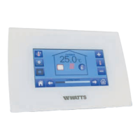
• Central Unit BT-CT02 RF
• Receivers BT-WR02 HC RF to control the boiler
• Receivers BT-WR02 RF (or BT-FR02 RF) to control the pumps (if needed)
• Receivers BT-WR02 RF (or BT-FR02 RF) to control the electrical heaters
• Thermostatic Heads BT-TH02 RF
VIRTUAL – RF CONNECTION:
Zone 1 1 Pair each thermostat to each zone of the BT-M6Z02 RF.
One thermostat can drive several zones.
2 Pair in master mode each BT-M6Z02 RF to the Central Unit BT-CT02 RF.
Name the virtual rooms in the BT-CT02 RF and select the hydraulic circuit.
BT-WR02 HC RF
BT-WR02 HC RF
Option
ZONE 1
BT-D02 RF
BT-TH02 RF
ZONE 2
BT-D02 RF
ZONE 3
BT-WR02 HC RF
BT-CT02 RF
UP TO SIX
BT-M6Z02 RF

 Loading...