Fastrack M1306B User Guide
General Presentation
confidential © Page: 22 / 65
This document is the sole and exclusive property of WAVECOM. Not to be distributed or divulged
without prior written agreement.
WM_PRJ_M13_UGD_001 -003 November 11, 2006
Table 1: Power supply connector pin description
Pin # Signal I/O I/O type Description Comment
1 V+BATTERY I Power
supply
Battery voltage input:
5.5 V Min.
13.2 V Typ.
32 V Max.
High current
2 GND Power
supply
Ground
3 GPIO4 I/O CMOS/2X General Purpose
Input/output
4 GPIO5 I/O CMOS/2X General Purpose
Input/output
Warning
:
Both pin 3 and pin 4 are used by GPIO interface. It is strictly prohibited to connect
them to any power supply at the risk of damage to the M1306B.
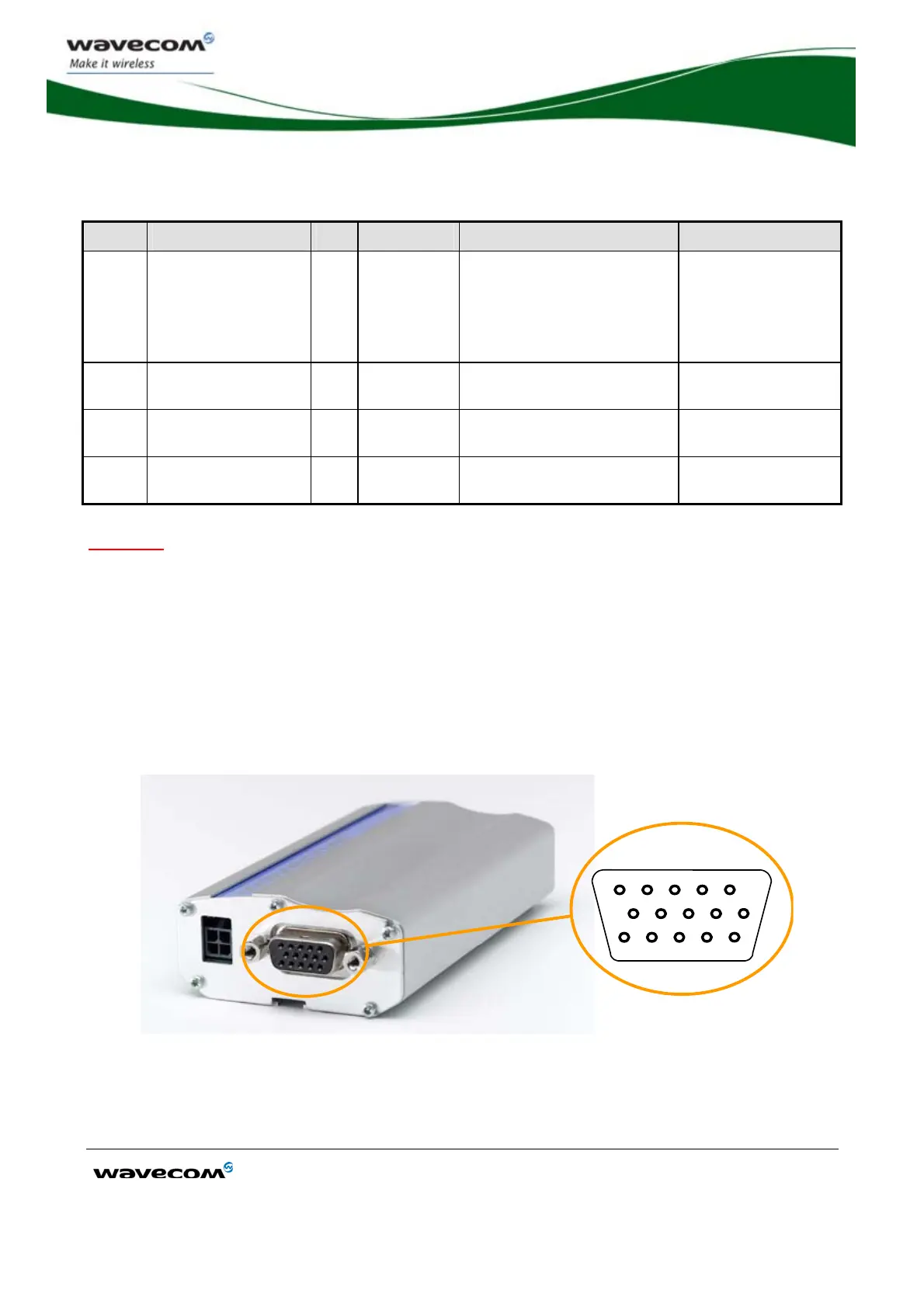
3.2.1.3 Sub HD 15-pin Connector
The Sub D high density 15-pin connector is used for:
• RS232 serial link connection,
• Audio lines (microphone and speaker) connection,
• BOOT and RESET signal connection.
1 2 3 4 5
6 7 8 9 10
15
14 13 11 12
Figure 8: Sub HD 15-pin connector