Fastrack M1306B User Guide
Functional Description
confidential © Page: 46 / 65
This document is the sole and exclusive property of WAVECOM. Not to be distributed or divulged
without prior written agreement.
WM_PRJ_M13_UGD_001 -003 November 11, 2006
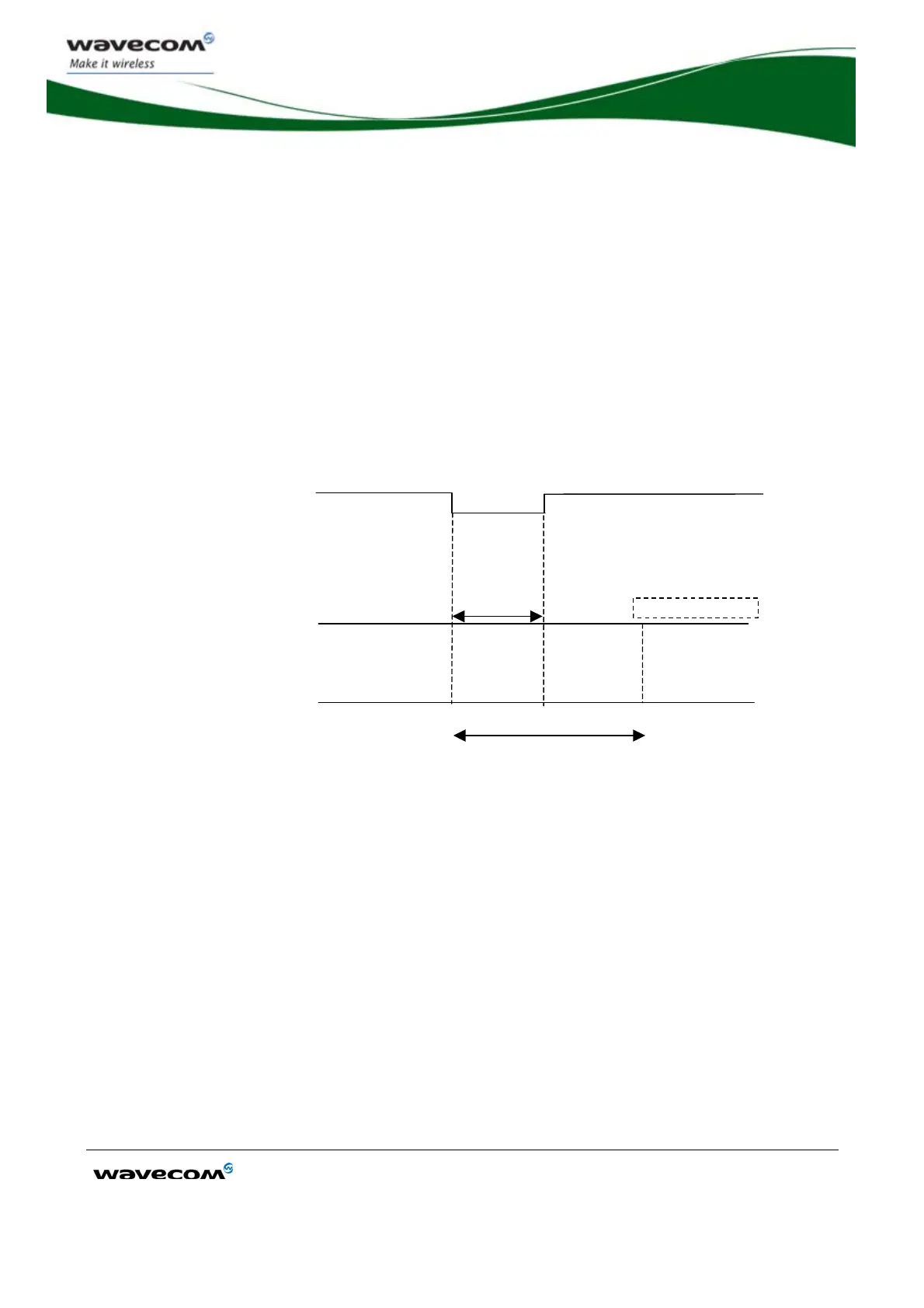
7.6.2 Reset Sequence
To activate the "emergency" reset sequence, the RESET signal has to be set to low for
500 µs minimum.
As soon as the reset is done, the AT interface answers "OK" to the application. For
this, the application must send
AT↵.
If the application manages hardware flow control, the AT command may be sent
during the initialization phase. Another solution is to use the
AT+WIND command to
get an unsolicited status from the M1306B.
For further details, refer to AT commands "AT Commands Interface Guide" [7].
RESET mode
I
BB+RF
=20
to 40 mA
EXTERNAL RESET
STATE OF WIRELESS CPU
®
WIRELESS CPU
®
READY
Min:500
s
Typ: 2 ms
T answers “OK”
WIRELESS CPU
®
READY
SIM and network dependent
WIRELESS
CPU
®
ON
I
BB+RF
<120 mA
without loc update
Figure 15: Reset sequence diagram
7.7 Audio
Audio interface is a standard one for connecting a phone handset.
Echo cancellation and noise reduction features are also available to improve the audio
quality in case of hand-free application.
7.7.1 Microphone Inputs
The microphone inputs are differential ones in order to reject common mode noise
and TDMA noise.
They already include the convenient biasing for an electret microphone (0.5 mA and 2
Volts) and are ESD protected.