Home
Wavecom
Computer Hardware
FASTRACK M1306B
Wavecom FASTRACK M1306B User Manual
5
of 1
of 1 rating
67 pages
Give review
Manual
Specs
To Next Page
To Next Page
To Previous Page
To Previous Page
Loading...
Fastrack M1306B User Guide
Technical Characteristics
confidential ©
Page: 49 / 65
This document is the sole and exclusive property
of WAVECOM. Not to be distributed or divulged
without prior written agreement.
WM_PRJ_M13_UGD_001 -003
November 11, 2006
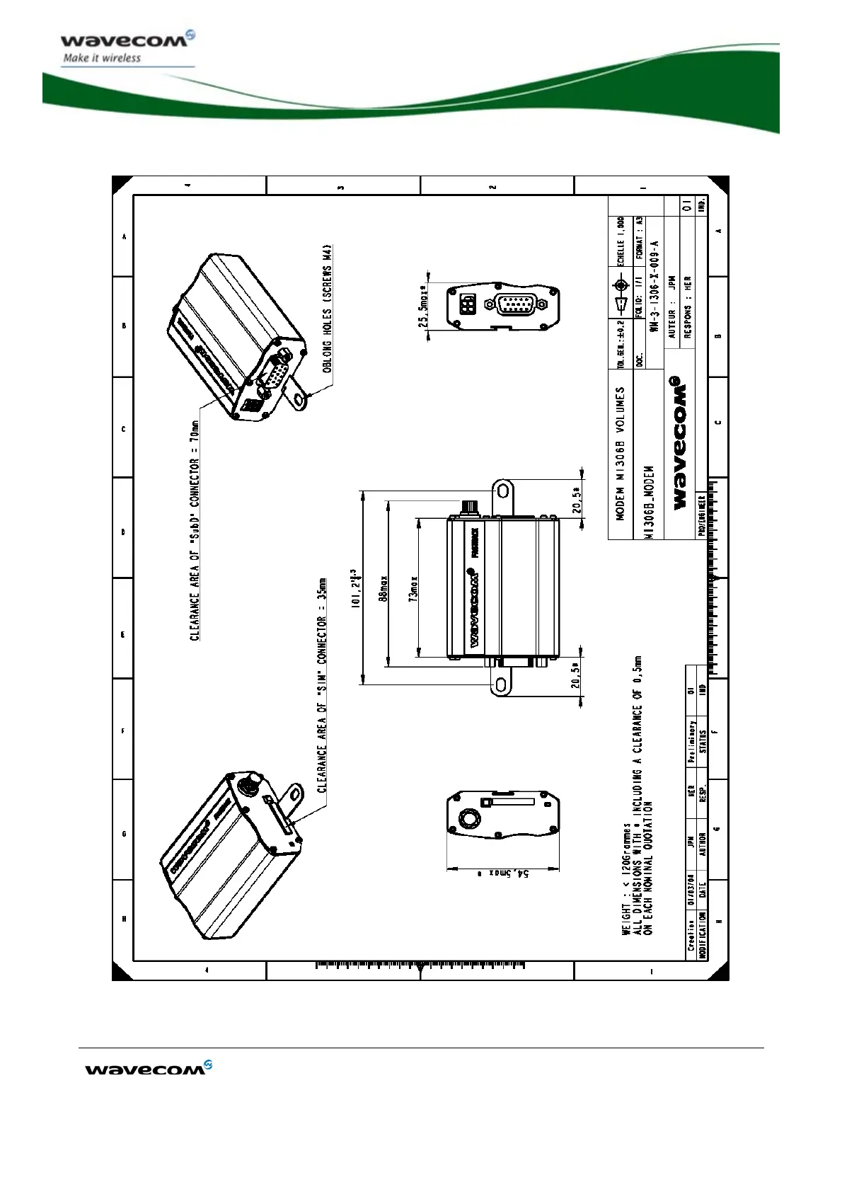
Figure 16: Dimensioning diagram
49
51
Table of Contents
Default Chapter
1
User Guide
1
Document History
3
Overview
4
Cautions
6
Trademarks
6
Copyright
6
Web Site Support
7
Table of Contents
8
Contents
8
List of Figures
11
List of Tables
12
1 References
13
Reference Documents
13
Open at ® Software Documentation
13
AT Software Documentation
13
Other Documents
13
Abbreviations
14
2 Packaging
17
Contents
17
Figure 1: Complete Package Contents
17
Packaging Box
18
Figure 2: Packaging Box
18
Production Sticker
19
Figure 3: Production Sticker
19
3 General Presentation
20
Description
20
Figure 4: Fastrack M1306B General Description
20
Figure 5: Fastrack M1306B Holding Bridles
21
External Connections
22
Connectors
22
Antenna Connector
22
Power Supply Connector
22
Figure 6: SMA Connector for Antenna Connection
22
Figure 7: Power Supply Connector
22
Sub HD 15-Pin Connector
23
Figure 8: Sub HD 15-Pin Connector
23
Table 1: Power Supply Connector Pin Description
23
Table 2: Sub HD 15-Pin Connector Description
24
Power Supply Cable
25
Figure 9: Power Supply Cable
25
4 Basic Features and Services
26
Table 3: Basic Features of the M1306B
26
5 Using the M1306B Wireless Cpu
28
Getting Started
28
Mount the M1306B
28
Set up the M1306B
28
Figure 10: M1306B Mounting
28
Check the Communication with the M1306B
29
Reset the M1306B
30
Specific Recommendations When Using the M1306B on Trucks
30
Recommended Power Supply Connection on Trucks
30
Technical Constraints on Trucks
31
Figure 11: Recommended Power Supply Connection on Trucks
31
M1306B Operational Status
32
Figure 12: Example of Electrical Connection Which May Dramatically Damage the M1306B
32
Echo Function Disabled
33
Table 4: M1306B Operational Status
33
Verify the Received Signal Strength
34
Check the Pin Code Status
34
Table 5: Values of Received Signal Strength
34
Table 6: AT+CPIN Responses
34
Verify the M1306B Network Registration
35
Table 7: Values of Network Registration
35
Main at Commands for the Wireless CPU
36
Table 8: Main Usual at Commands for the Wireless CPU
36
Firmware Upgrade Procedure
37
6 Troubleshooting
38
No Communication with the M1306B through the Serial Link
38
Table 9: Solutions for no Connection with M1306B through Serial Link
38
Receiving "ERROR" Message
39
Receiving "NO CARRIER" Message
39
Table 10: Solutions for "NO CARRIER" Message
40
Table 11: Interpretation of Extended Error Code
41
7 Functional Description
42
Architecture
42
Figure 13: Functional Architecture
42
Power Supply
43
General Presentation
43
Protections
43
RS232 Serial Link
43
Autobauding Mode
44
Figure 14: RS232 Serial Link Signals
44
Pin Description
45
General Purpose Input/Output (GPIO)
45
Boot
46
Reset
46
General Presentation
46
Reset Sequence
47
Audio
47
Microphone Inputs
47
Figure 15: Reset Sequence Diagram
47
Speaker Outputs
48
8 Technical Characteristics
49
Mechanical Characteristics
49
Table 12: Mechanical Characteristics
49
Figure 16: Dimensioning Diagram
50
Electrical Characteristics
51
Power Supply
51
Table 13: Electrical Characteristics
51
Table 14: Effects of Power Supply Defect
51
Table 15: Power Consumption (1*)
52
Audio Interface
53
Table 16: Audio Parameters Caracteristics
53
Table 17: Microphone Inputs Internal Audio Filter Characteristics
53
Table 18: Recommended Characteristics for the Microphone
53
General Purpose Input/Output
54
SIM Interface
54
RESET Signal
54
Table 19: Recommended Characteristics for the Speaker
54
Table 20: Operating Conditions
54
Table 21: SIM Card Characteristics
54
Table 22: Electrical Characteristics
54
RF Characteristics
55
Frequency Ranges
55
Table 23: Operating Conditions
55
Table 24: Frequency Ranges
55
RF Performances
56
Table 25: Receiver and Transmitter RF Performances
56
External Antenna
57
Environmental Characteristics
57
Table 26: External Antenna Characteristics
57
Table 27: Ranges of Temperature
57
Table 28: Environmental Standard Constraints
58
Conformity
60
Protections
60
Power Supply
60
Overvoltage
60
Esd
61
Miscellaneous
61
9 Safety Recommendations
62
General Safety
62
Vehicle Safety
63
Care and Maintenance
63
Your Responsibility
64
10 Recommended Accessories
65
Table 29: List of Recommended Accessories
65
11 Online Support
66
5
Based on 1 rating
Ask a question
Give review
Questions and Answers:
Need help?
Do you have a question about the Wavecom FASTRACK M1306B and is the answer not in the manual?
Ask a question
Wavecom FASTRACK M1306B Specifications
General
Brand
Wavecom
Model
FASTRACK M1306B
Category
Computer Hardware
Language
English