WM_PRJ_M13_UGD_001 - 001
20th July 2004
© 2004
All rights reserved
Wavecom Confidential & Proprietary Information
Page: 41 / 55
This document is the sole and exclusive property of WAVECOM. Not to be distributed or divulged
without prior written agreement.
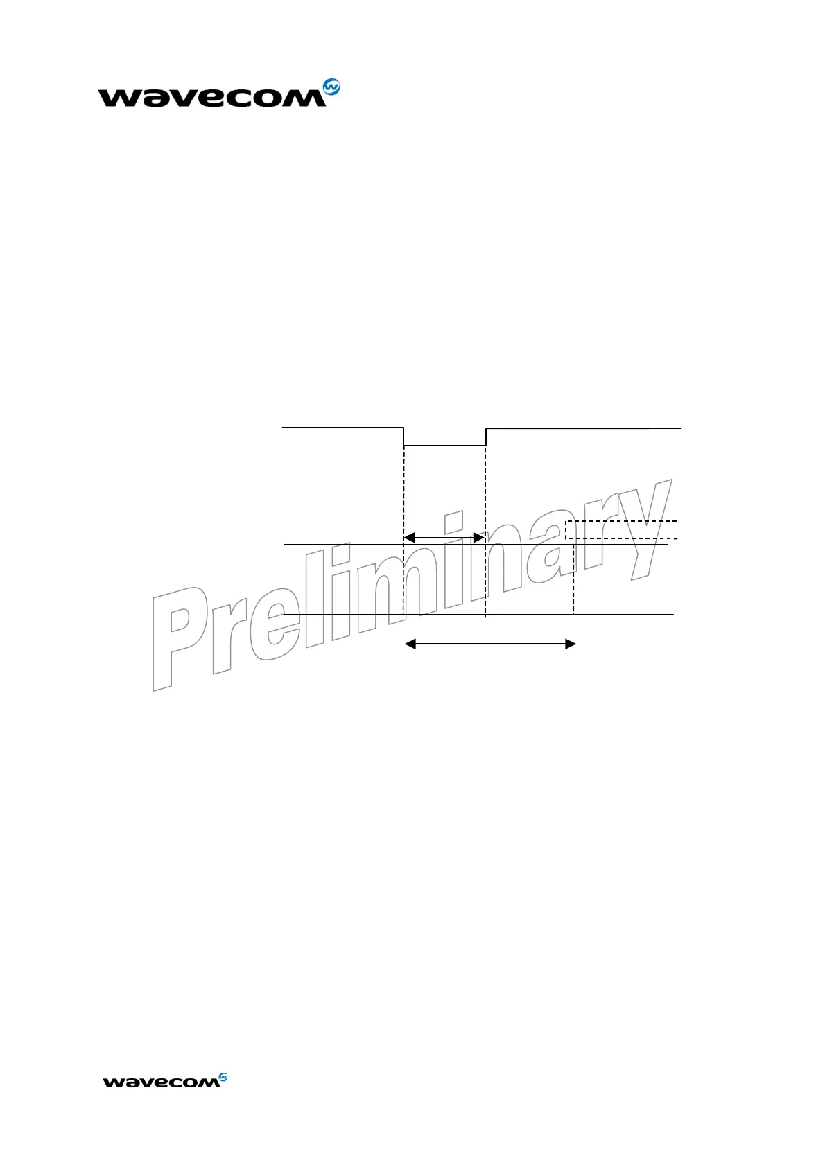
7.6.2 Reset sequence
To activate the « emergency » reset sequence, the RESET signal has to be set to
low for 500 µs minimum.
As soon as the reset is complete, the AT interface answers « OK » to the
application. For this, the application has to send
AT
↵
.
If the application manages hardware flow control, the AT command can be sent
during the initialisation phase. Another solution is to use the AT+WIND
command to get an unsollicited status from the modem.
For further details, refer to AT commands documentation [1].
RESET mode
I
BB+RF
=20
to 40 mA
EXTERNAL RESET
STATE OF THE MODEM
Modem READY
Min:500
µ
s
Typ: 2 ms
AT answers “OK”
Modem READY
SIM and network dependent
Modem ON
I
BB+RF
<120 mA
without loc update
Figure 15: Reset sequence diagram