208 CHAPTER 24 CLICK 304
Physical Features
e Click 304 has several communication ports, as well as features for conguration.
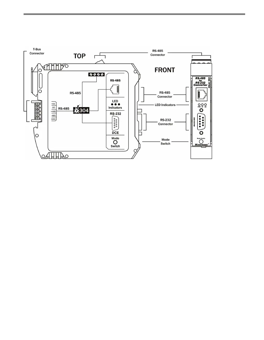
Figure 24.2 – Diagram of the Click 304
Communication Ports
e back of the Click 304 features a 5-position connector that plugs into a T-bus connector
and provides power and RS-485 communication to the device. It also passes RS-485 com-
munication from the Click 304 to all other devices on the T-bus.
e top of the device has a pluggable screw terminal block that features four terminals—one
-485, one +485 and two grounds—for wiring RS-485 communication. is screw terminal
block can be removed for easy preinstallation wiring. It will not be necessary, however, to
wire RS-485 through the screw terminal block if the device is connected to a T-bus with
uninterrupted RS-485 communication.
e front of the Click 304 features a DB-9 connector and an RJ-11 connector for RS-232
and RS-485 communication. A straight-through cable can be used to connect from the
RS-232 DB-9 connector to a computer so that the device can be congured using Click
Supervisor. An RJ-11 cable can be connected from the front of the Click 304 to the front of
the Click 172/174 contact closure cards.
Any data on one port will be transmitted simultaneously on all other ports.