80 CHAPTER 9 CLICK 110
Physical Features
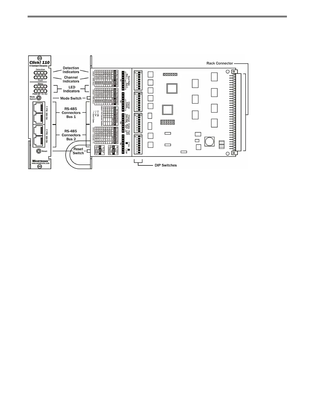
e following sections describe the physical features of the Click 110 card.
Figure 9.2 – Diagram of the Click 110
Communication Ports
e Click 110 contains two independent serial communications ports. Each port is made
up of two RJ-11 connectors, which make it simple to daisy-chain multiple Click 110 cards
together and create a RS-485 bus. e two RJ-11 RS-485 data buses can be connected to a
SmartSensor through a Click 200 surge protection module, or through a serial data con-
verter.
Typically, one bus is used to report vehicle data, and the other is used for conguration. As
both buses are identical it does not matter which is used for data or conguration. Alterna-
tively, a single bus could be used for both data and conguration, but data reporting would
be temporarily halted during conguration. During this time, the Click 110 will enter fail-
safe mode if vehicle data is not reported for ten seconds.
LEDs
e faceplate of the Click 110 has four banks of LEDs. e top bank is used for detection in-
dication, the second bank for fault indication, the third for menu indication, and the fourth
for menu indication as well as operation states.