CHAPTER 9 CLICK 110 81
Detection
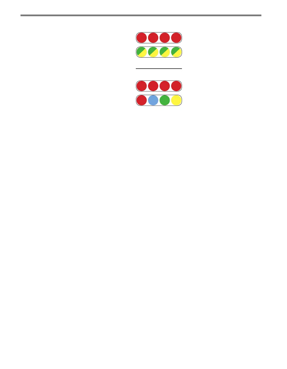
1 2 3 4
Fault
Menu
PWR MF TD RD
1 2 3 4
Figure 9.3 – Click 110 LEDs
e detection indicator LEDs consist of four red LEDs numbered 1–4, each representing
a channel (see Figure 9.3). An illuminated LED indicates the presence of a vehicle. ese
indicators are dedicated to detection and have no other display purposes.
e fault indicator LEDs consist of four dual-color (green / yellow) LEDs numbered 1–4,
each representing the channel with the corresponding number (see Figure 9.3).
Illuminated green LED – Indicates a no-fault condition.
Illuminated yellow LED – Indicates a fault condition which has existed for less than
one minute.
Extinguished LED – Indicates a fault condition which has existed for more than one
minute.
e menu indicator LEDs include two rows of LEDs (see Figure 9.3). e lower row con-
tains Level 1 indicators, while the upper row contains Level 2 indicators. Each level consists
of four LEDs numbered 1–4 (le to right). Level 1 LEDs display which menu is active. ese
Level 1 LEDs are dual-purpose, each indicating both menu selection as well as a normal
operation state when not in Menu mode. e normal operation state functions include:
Red (PWR) – Indicates the presence of power to the device.
Blue (MF) – Illuminates when the master fault output is in the no-fault condition. e
LED is extinguished in the fault condition.
Green (TD) – Indicates serial communication transmit data (from the Click 110) on
either RS-485 bus 1 or RS-485 bus 2.
Yellow (RD) – Indicates serial communication receive data (to the Click 110) on either
RS-485 bus 1 or RS-485 bus 2.
Level 2 LEDs display conguration options. All level 2 LEDs are red. ese LEDs are dedi-
cated to menu operation, and are extinguished when the menu is not active.