102 CHAPTER 9 SETUP OUTPUT COMMUNICATIONS
Select port to transmit output
is control allows you to manually select which of the SmartSensor Advance’s commu-
nication ports will be used for data pushing. e available options are None, Port 1 and
Port 2.
In standard installations, Port 2 is an RS-485 port and is designated as the data bus. Data
push will automatically be set up when you auto-congure a contact closure card (Click
models 100/112/114/172/174). With version 3.0.2 and later, the default port is set at 2 and
the default format is Z4 - Click 112/114.
However, you do not have to use the default Port 2. If you select Port 1, be aware that in
standard installations, Port 1 is designated as the control bus. For SS200V sensors, the
control bus is an RS-485 port usually connected to the bridge port of a Click 222 and is
shared with other devices.
e SmartSensor 6-conductor cable is used with SS200V sensors; the blue striped wires
are for Port 1 and the orange striped wires are for Port 2. However, remember that with the
original SS200 sensor or with the SS200VR (retrot) sensor, port one is an RS-232 port.
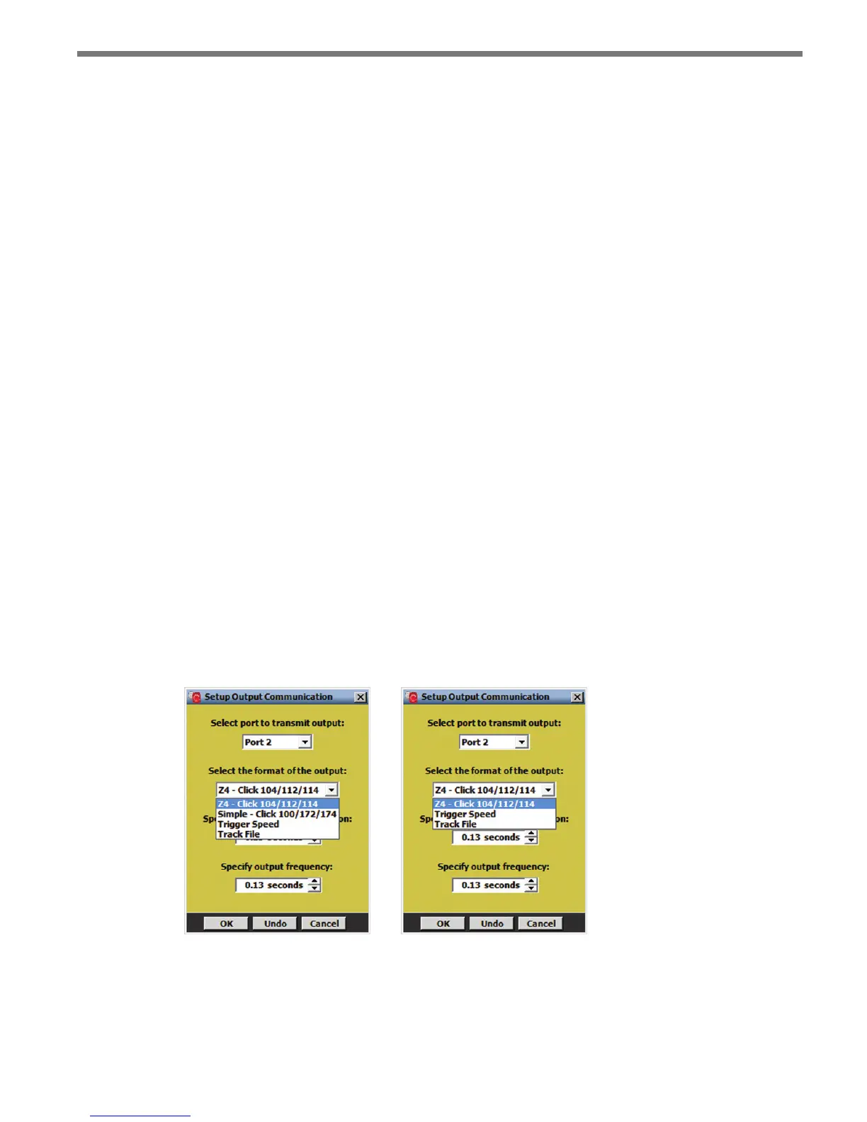
Select the format of the output
is control allows you to manually select which type of data will be transmitted by Smart-
Sensor Advance. e options are:
Z4 – Click 112/114
Simple – Click 172/174 (not available for SmartSensor Advance Extended Range)
Trigger Speed
Track File
Figure 9.2 – Select Output Format for Advance (left) and Advance Extended Range (right)