52 CHAPTER 5 SENSOR SETTINGS
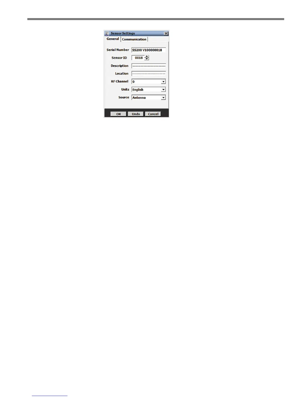
Figure 5.2 – General Tab
Serial Number – Contains the sensor serial number and can only be edited if you are
in the Advanced Sensor Setup mode (conatct Wavetronix Technical Services for more
information).
Sensor ID – Allows you to enter a multi-drop address for the sensor. e ID default
is the last four digits of the sensor serial number. e sensor ID can be changed, but
no two sensors should have the same ID; the ID must be unique for all sensors on a
multi-drop bus.
Description – Allows you to enter a description for each sensor (i.e. its function, ap-
plication or intended use). Limited to 32 characters.
Location – Allows you to enter the location of the sensor or the approach. Limited to
32 characters.
RF Channel – Displays which radio frequency channel (or non-interference channel)
the device is transmitting on. Using multiple SmartSensor Advance devices in close
proximity will require each one to be set to a dierent RF channel. Similarly, using
multiple SmartSensor Advance Extended Range devices in close proximity will re-
quire each one to be set to a dierent RF channel. However, a SmartSensor Advance
device will not interfere with a SmartSensor Advance Extended Range device, even
if they are on the same RF channel. is is because the hardware used to transmit the
Digital Wave Radar signal is congured dierently on the dierent devices.
Units – Allows you to display either English (mph/feet) or metric (kph/meters) units.
Source – In normal use, the source is always the radar Antenna. However, in some
cases, other sources may be used for demonstrations or evaluations. When the source
is switched to Diagnostic, the antenna is no longer used. Instead, a predetermined
sequence of trac will appear. is setting will always return to Antenna after reboot-
ing the sensor.
Communication Tab
e Communication tab is used to specify baud rate and response delay for the sensor’s
RS-485 ports (see Figure 5.3).