CHAPTER 7 CHANNELS-ALERTS-ZONES 77
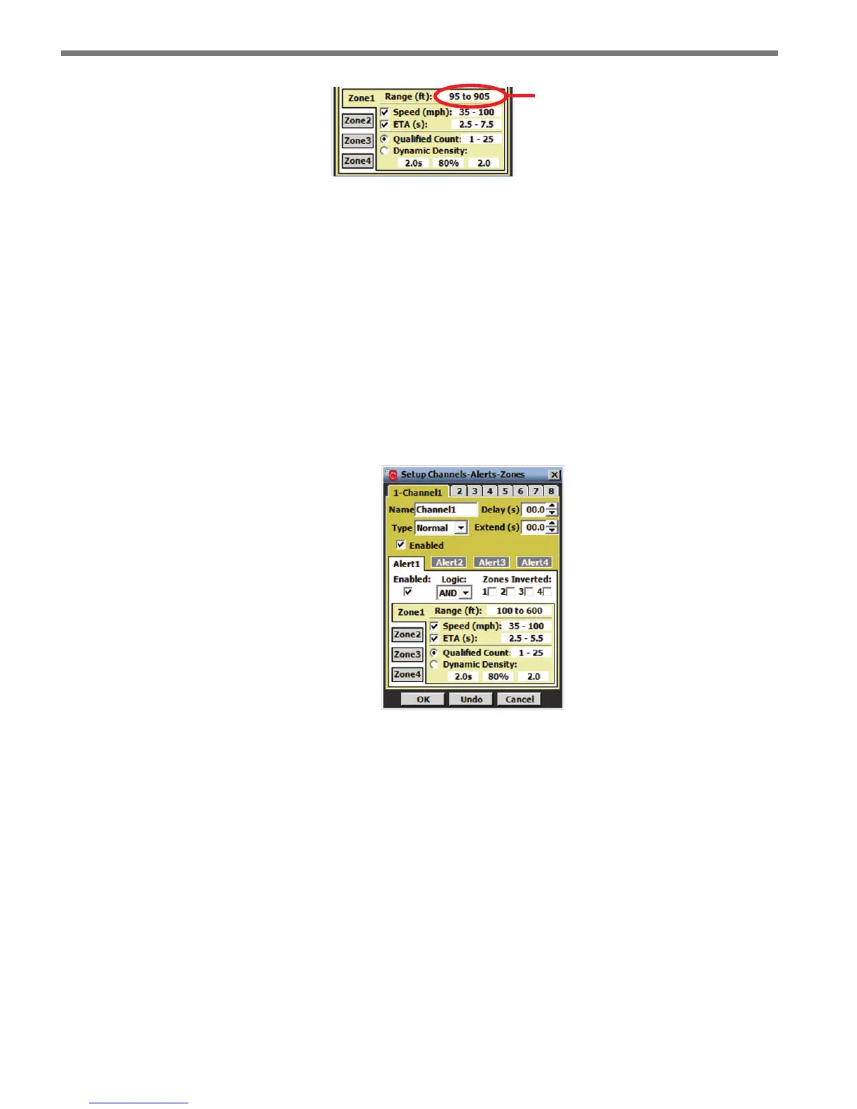
Click here
to open the
range editor
Figure 7.16 – Zone Configuration
Below is a description of each parameter in the zone section of the CAZ Setup screen (see
Figure 7.16).
Range (ft)
A zone is enabled when its range is dened. When a zone is enabled, the zone section of
the setup screen turns yellow; when a zone is disabled, the zone section turns light gray. A
detection must be within a zone’s range limits in order to activate that zone’s output. All
zone ranges in a given alert are congured in a single screen and may not overlap in range.
Click in the zone range display next to the range label to open the zone range editor (see
Figure 7.17).
Figure 7.17 – Zone Range Editor
To add (enable) a zone, drag the desired zone icon from the zone well to the roadway; to re-
move (disable) a zone, drag it from the roadway to the zone well (or anywhere o the road-
way). If a zone is moved to an invalid location, it will be returned to its previous location.
To change the range of a zone, drag the blue triangle markers up or down the roadway or
click the up/down arrows on either side of the screen (see Figure 7.18). e zone can be
placed anywhere on the roadway by clicking anywhere inside the zone and dragging it. e
minimum range is 50 ft. (15.2 m) from the sensor and the maximum range is 600 ft. (152.4
m) from the sensor.