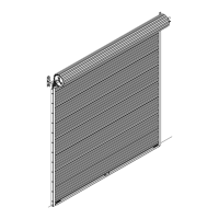
(4) 1/4” - 20 x 1-7/8”
Carriage bolts
(4) 1/4” - 20
Flange hex nuts
Top fixture
slide
Top section
Top fixture
base
1-1/8”
= 3-1/8”
Top rail
Short stem
track roller
Slot
Loosen the 1/4”-20
flange hex nuts
(4) 1/4” - 20
Flange hex nuts
Top fixture slide
Short stem track roller
Top section
Top fixture
base
1-1/8”
= 3-1/8”
Top rail
(4) 1/4” - 20 x 1-7/8”
Carriage bolts
Slot
Loosen the
5/16”-18 Hex nut
NOTE: Ensure the top fixture slide is able to slide along the top fixture base. If needed, loosen
the 1/4” - 20 flange hex nuts.
Repeat the same process for the right hand side. The top fixtures will be tightened and
adjusted later, in step, Adjusting Top Fixtures. Insert a short stem track roller into each of the
top fixture slides.
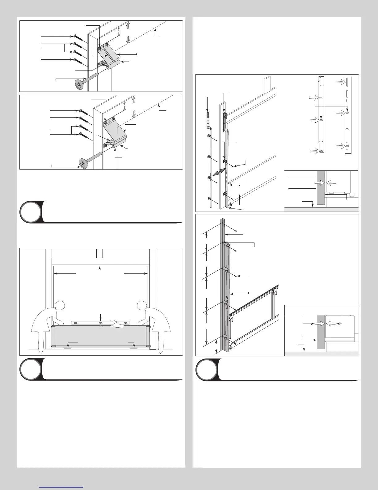
Positioning Bottom Section
8
Center the bottom section in the door opening. Level the section using wooden shims (if
necessary) under the bottom section. When the bottom section is leveled, temporarily hold it
in place by driving a nail into the jamb and bending it over the edge of the bottom section on
both sides.
Weather seal (If applicable)
Level
Bottom section
Wooden shims (If necessary)
Attaching Vertical Tracks To Jambs
9
NOTE: Depending on your door, you may have Fully Adjustable Flag Angles, Riveted Vertical
Track Assemblies or you may have Angle Mount Vertical Track Assemblies. Refer to Package
Contents / Breakdown of Parts, to determine which Flag Angles / Vertical Track Assemblies
you have.
IMPORTANT: IF YOUR DOOR IS TO BE INSTALLED PRIOR TO A FINISHING CONSTRUCTION
OF THE BUILDING’S FLOOR, THE VERTICAL TRACKS AND THE DOOR BOTTOM SECTION
ASSEMBLY SHOULD BE INSTALLED SUCH THAT WHEN THE FLOOR IS CONSTRUCTED, NO
DOOR OR TRACK PARTS ARE TRAPPED IN THE FLOOR CONSTRUCTION.
IMPORTANT: THE TOPS OF THE VERTICAL TRACKS MUST BE LEVEL FROM SIDE TO SIDE.
IF THE BOTTOM SECTION WAS SHIMMED TO LEVEL IT, THE VERTICAL TRACK ON THE
SHIMMED SIDE MUST BE RAISED THE HEIGHT OF THE SHIM.
NOTE: Make sure the counterbalance lift cable is located between the track rollers and the
door jamb.
Starting on the left hand side, remove the nail holding the bottom section to jamb. Position
the left hand vertical track assembly / angle mount assembly over the track rollers of the bot-
tom section. Make sure the counterbalance lift cable is located between the track rollers and
the door jamb. Drill 3/16” pilot holes into the door jamb for the lag screws. Loosely fasten
vertical track assembly / angle mount assembly to the jamb using 5/16” x 1-5/8” lag screws.
FOR 2” TRACK: Tighten fasteners, securing the bottom jamb bracket in the vertical track
assemblies / bottom slot in the angle mount to jamb, maintain 3/8” to 5/8” spacing, between
the bottom section and vertical track.
FOR 3” TRACK: Tighten fasteners, securing the bottom jamb bracket in the vertical track
assemblies / bottom slot in the angle mount to jamb, maintain 1/2” to 3/4” spacing, between
the bottom section and vertical track.
2” Vertical track
spacing (3/8” to 5/8”)
3” Vertical track
spacing (1/2” to 3/4”)
Bottom
section
Floor
Track roller
Fully
Adjustable
flag angle
Jamb
bracket
Riveted track
flag angle
Riveted
flag angle
5/16” x 1-5/8”
Lag screws
Bottom
section
Track
rollers
Vertical track
assembly
Lag
screw
locations
Fully Adjustable
flag angle
For 2” Track: 3/8” to 5/8” spacing
For 3” Track: 1/2” to 3/4” spacing
Bottom section
Vertical track
Floor
Angle mount
vertical track
assembly
Bottom
section
5/16” x 1-5/8”
Lag screws
Vertical track
NOTE: Typical
fastener / slot
spacing.
24”
30” To 18”
13”
24” O.C.
Max.
10”
Stacking Sections
10
NOTE: Refer to door section identification, located in the pre-installation section of this
manual to determine what size section you need to use as your intermediate I (second), inter-
mediate II (third), intermediate III (fourth), Intermediate IV (fifth) and if applicable Intermediate
V (sixth). Measure your section to make sure it is the correct height as indicated on the chart.
NOTE: Make sure graduated end and center hinges are flipped down, when stacking another
section on top.
With assistance, lift second section and guide the track rollers into the vertical tracks. Keep-
ing the sections vertically aligned, lower section until it is seated against bottom section.
11