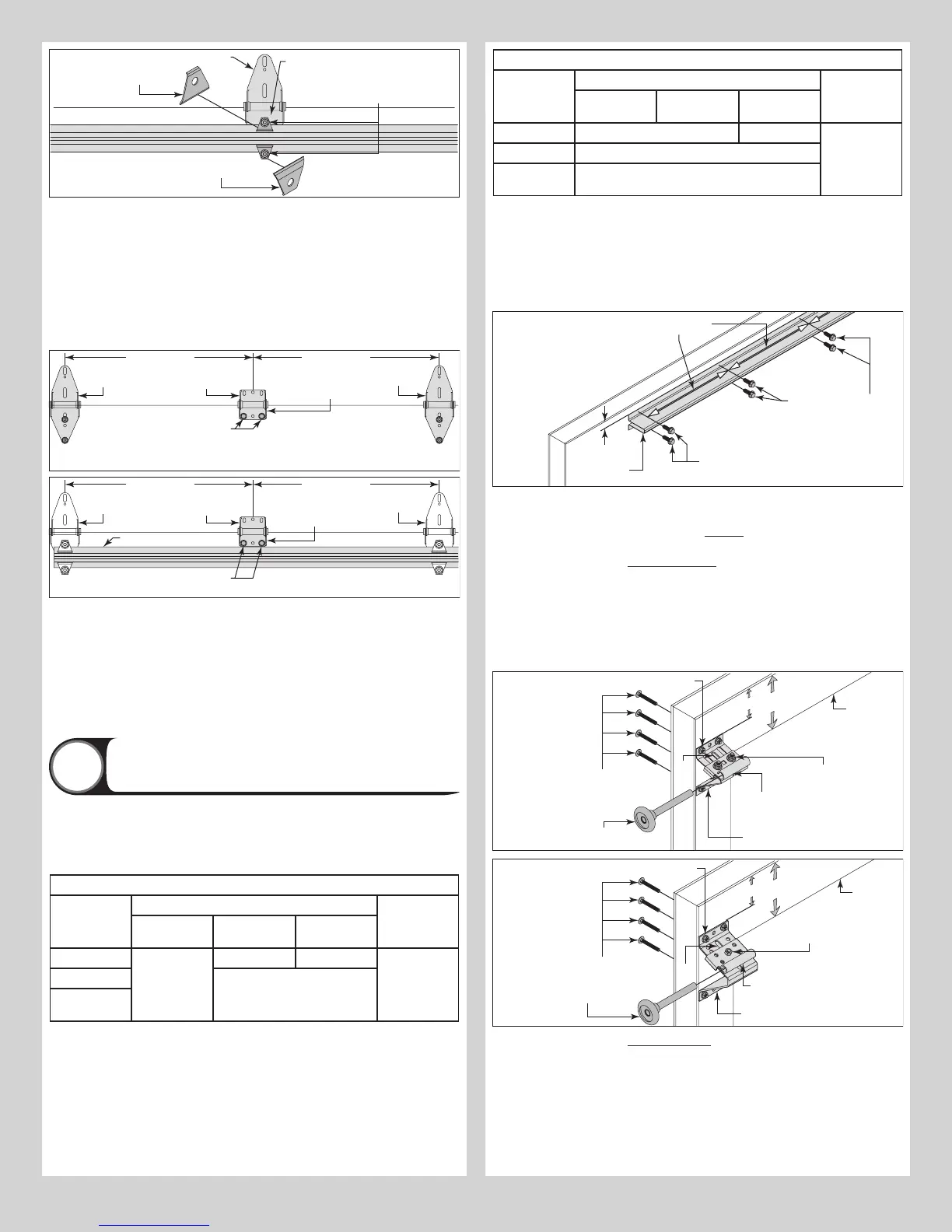
Lower hinge leaf
(2) 1/4” - 20 x 1-7/8”
and (2) 1/4” - 20 Flange hex nuts
Intermediate
section
(1) Strut
clip
(1) Strut
clip
NOTE: If you don’t have half center hinges, then skip this part of the step. Refer to Package
Contents / Breakdown Of Parts, to determine if you have half center hinges.
Using a tape measure, position the half center hinges equally spaced in between the center
hinges and the graduated end hinges. Position the holes of the lower hinge leaf at the top rail
of the bottom section. Using the half center hinge as a template, drill pilot holes, 1” deep into
the Intermediate section with a 1/8” drill bit (if needed).
IMPORTANT: BE EXTREMELY CAREFUL NOT TO DRILL THRU THE SECTION. ONLY DRILL 1”
DEEP.
Attach the lower hinge leaf of the center hinge to the Intermediate section using (2) 1/4” - 14
x 1” lag screws. Repeat for other half center hinge(s).
(2) 1/4” - 14 x 1” Lag screws
Intermediate
section
Half center hinge
Lower hinge leaf
Center hinge
Graduated
end hinge
Equally spaced Equally spaced
(2) 1/4” - 14 x 1” Lag screws
Intermediate
section
Half center hinge
Lower hinge leaf
Center hinge
Graduated
end hinge
Equally spaced Equally spaced
LONG STRUT
If you have single graduated end hinges, insert a short stem track roller / short stem tandem
track roller (if included) into the hinge tube on each side.
If you have double graduated end hinges, insert a long stem track roller / short stem tandem
track roller (if included) into the hinge tubes on each side.
IMPORTANT: WHEN PLACING TRACK ROLLERS / TANDEM TRACK ROLLER (IF INCLUDED)
INTO GRADUATED END HINGES NUMBER 2 AND HIGHER, THE TRACK ROLLER / TANDEM
TRACK ROLLER (IF INCLUDED) GOES INTO TUBE FURTHEST AWAY FROM SECTION.
If applicable, repeat the same process for the other Intermediate sections, except for the top
section.
Attaching Top Fixtures And Strut To Top Sec-
tion
7
NOTE: Refer to door section identification, located in the pre-installation section of this
manual to determine what size section you need to use as your top section. Measure your
section to make sure it is the correct height as indicated on the chart.
NOTE: Refer to the Top Section Short Strut Strutting Schedule below, to determine the ap-
propriate strutting for your Top section.
Top Section Short Strut Strutting Schedule For Door Heights Less Than Or Equal to 8’0”
Door Models Door Width Location On Top
Section
Up To and In-
cluding 12’2”
From 12’3” To
16’0”
From 16’1” To
18’0”
105 / 106 N/A (1) Short N/A Top Of Section
110 / 116 (1) Short
310 / 311 / 314
/ 316
Top Section Short Strut Strutting Schedule For Door Heights Greater Than Or Equal to 8’1”
Door Models Door Width Location On Top
Section
Up To and In-
cluding 12’2”
From 12’3” To
16’0”
From 16’1” To
18’0”
105 / 106 (1) Short N/A Top Of Section
110 / 116 (1) Short
310 / 311 / 314
/ 316
(1) Short
Place the top section face down on a couple of sawhorses or flat clean/ smooth surface.
Lay a SHORT STRUT onto the top rail of the top section. Position the top of the strut 3/4”
downward from the top edge of the top section. Center the short strut from side to side on
the section surface. Drill pilot holes, 1” deep into the top section using a 1/8” drill bit.
IMPORTANT: BE EXTREMELY CAREFUL NOT TO DRILL THRU THE SECTION. ONLY DRILL 1”
DEEP.
Attach the strut using (1) 1/4” - 14 x 1” lag screw at each pre-drilled hole.
Top section
1/4” - 14 x 1”
Lag screws
SHORT
STRUT
3/4”
1/4” - 14 x 1” Lag screws
30” on centers
NOTE: Refer to Package Contents / Breakdown of Parts, to determine which Top Fixtures
Assemblies you have.
First, measure the width the top rail (5-3/16” or 3-1/8”) of the top section, to determine, the
proper location and the correct orientation of the top fixtures.
FOR TOP SECTIONS WITH A 5-3/16” TOP RAIL: Measure down from the top of the top
section 3-1/4” and make a small mark. Align the top of the top fixture assembly with the
mark previously made and even with the edge of the section.
NOTE: The slotted half of the top fixture assembly should be facing upwards.
USING THE TOP FIXTURE BASE AS A TEMPLATE, MARK AND PRE-DRILL (4) 9/32”
DIAMETER HOLES THROUGH THE TOP SECTION. ATTACH THE TOP FIXTURE BASE TO
THE TOP SECTION USING (4) 1/4” - 20 X 1-7/8” CARRIAGE BOLTS AND (4) 1/4” - 20
FLANGE HEX NUTS.
(4) 1/4” - 20 x 1-7/8”
Carriage bolts
(4) 1/4” - 20 Flange hex nuts
Top fixture
slide
Top section
Top fixture
base
3-1/4”
= 5-3/16”
Top rail
Short stem
Slot
Loosen the 1/4”-20
flange hex nuts
(4) 1/4” - 20 Flange hex nuts
Top fixture slide
Short stem track roller
Top section
Top fixture
base
Slot
3-1/4”
= 5-3/16”
Top rail
Loosen the
5/16”-18 Hex nut
(4) 1/4” - 20 x 1-7/8”
Carriage bolts
FOR TOP SECTIONS WITH A 3-1/8” TOP RAIL: Measure down from the top of the top sec-
tion 1-1/8” and make a small mark. Align the top of the top fixture assembly with the mark
previously made and even with the edge of the section.
NOTE: The slotted half of the top fixture assembly should be facing downwards.
Using the top fixture base as a template, mark and pre-drill (4) 9/32” diameter holes through
the top section. Attach the top fixture base to the top section using (4) 1/4” - 20 x 1-7/8”
carriage bolts and (4) 1/4” - 20 flange hex nuts.
10