5.1 TESTS
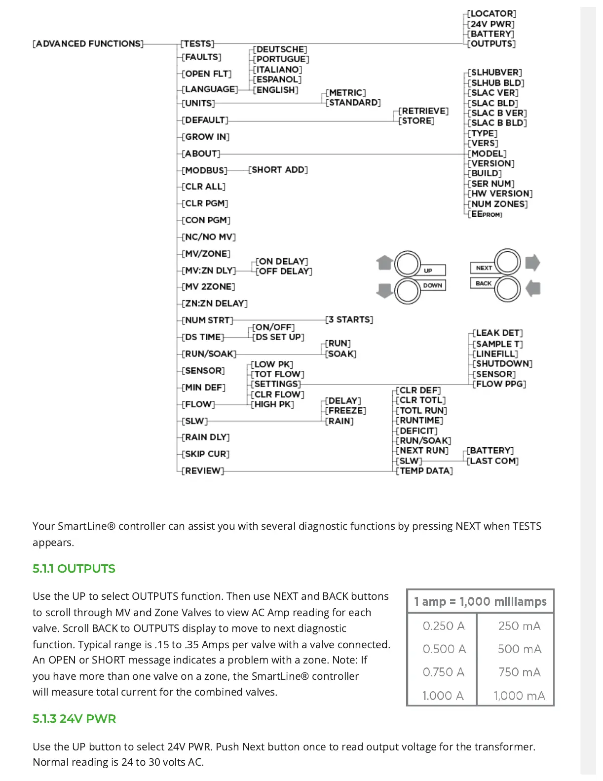
Your SmartLine® controller can assist you with several diagnosticfunctions by pressing NEXT when TESTS
appears.
5.1.1 OUTPUTS
Use the UP to select OUTPUTS function.Then use NEXT and BACK buttons
toscroll through MV and Zone Valves toview AC Amp reading for each
valve.Scroll BACK to OUTPUTS display tomove to next diagnostic
function.Typical range is .15 to .35 Amps pervalve with a valve connected.
An OPENor SHORT message indicates a problem with a zone. Note: If
youhave more than one valve on a zone, the SmartLine® controller
willmeasure total current for the combined valves.
5.1.3 24V PWR
Use the UP button to select 24V PWR. Push Next button once toread output voltage for the transformer.
Normal reading is 24 to30 volts AC.