Page 18 of 40 Webasto Charging Systems, Inc.
Intelligent Fast-Charging System GSE Installation Guide for the DVS300/330/400 and MVS330/400
31504-76-0101
4. Installation Instructions
Only authorized installers or authorized repair persons perform installation, maintenance, and repair work on
the unit.
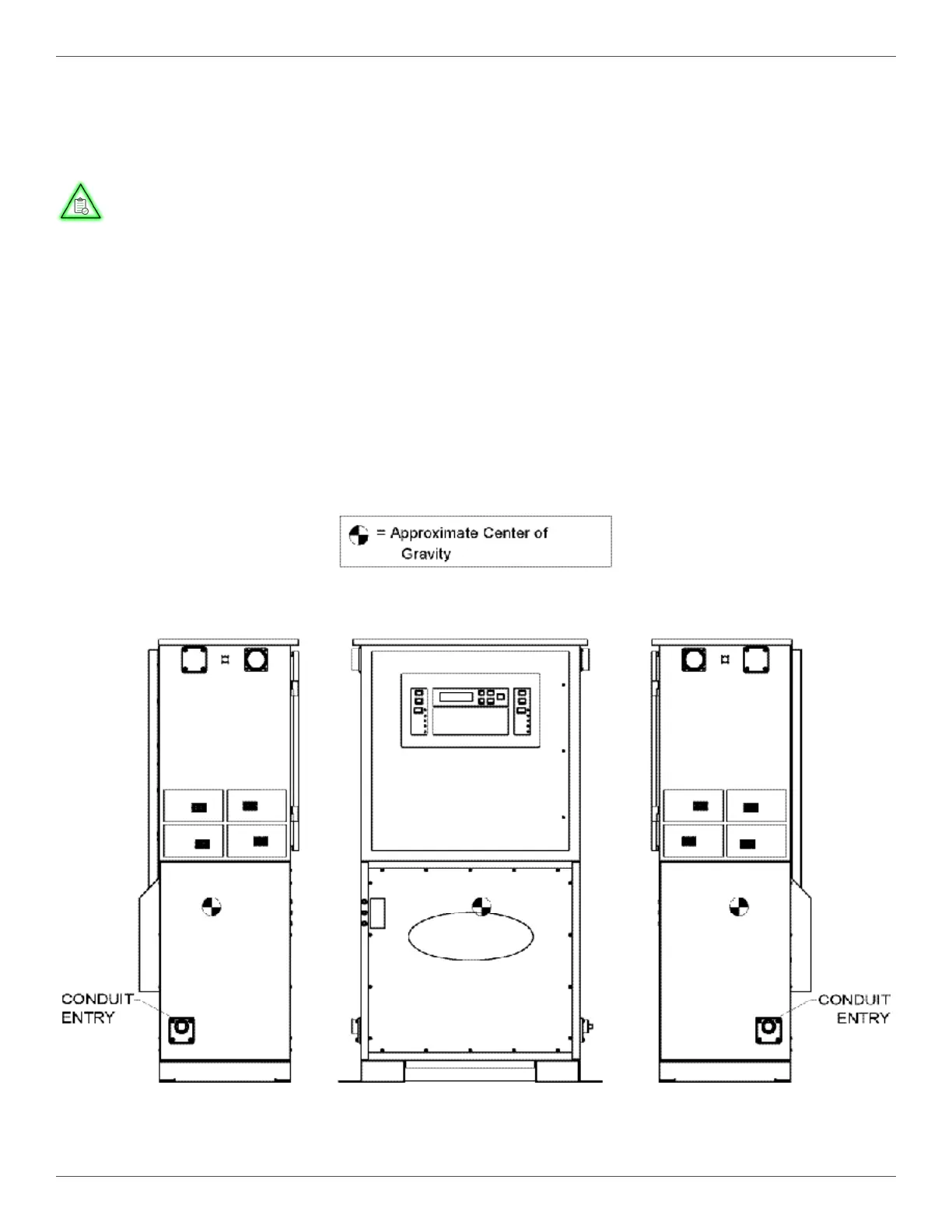
Figure 6 DVS300/330/400 Power (Conduit Entry) Locations
4.1. DVS 300/330/400
4.1.1. Mark the hole locations for the anchor bolts, using the mounting holes in the mounting footprint
as a guide, according to the specications (in Figure 3 [A]).
EQUIPMENT ACCESS
Be sure to use the proper size driver bits when removing or installing screws to avoid
stripping the heads. A driver with a clutch setting just sucient to drive the screws
should be used to install them. This setting will avoid stripping the threads or breaking
the threaded inserts. Screws should be started slowly, after aligning the holes, to avoid
cross threading.
NOTE
4.1.1.1. Conduit Connections
4.1.1.1.1. The conduit size is 1¼″ for AC input connections, for which 1¼-inch hubs are provided.
(See Figure 6 for conduit entry locations.)