Page 37 of 40 Webasto Charging Systems, Inc.
Intelligent Fast-Charging System GSE Installation Guide for the DVS300/330/400 and MVS330/400
31504-76-0101
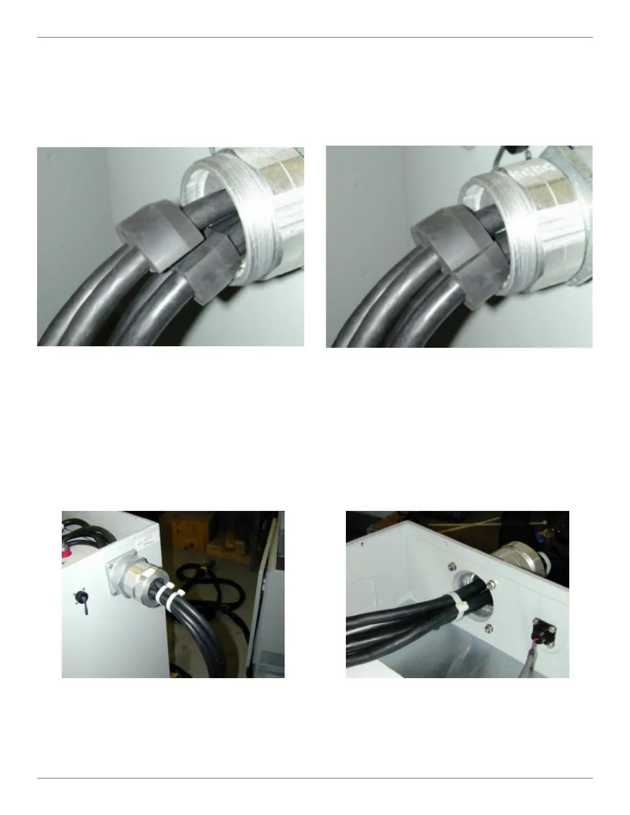
Figure 23 Power Station, Outside View Figure 24 Power Station, Inside View
Figure 21 Rubber Grommet Installation on
the Cables
Figure 22 Rubber Grommet Installation with the Two
Halves Lined Up
4.9.2.11. The grommet should be placed on the cables as close to the feedthrough as possible, with the
tapered side facing the hub connector body (4) (Figure 21).
4.9.2.12. Push the split rubber grommet (3) into the hub connector body (4), making sure that the two halves
line up and that there are no large gaps (Figure 22).
4.9.2.13. Slide the stainless steel washer (2) and threaded cap (1) up to the tting, and tighten the assembly
until the split rubber grommet (3) is tightly compressed.
4.9.2.14. Install two zip ties around the cables at 2" and 4" from the threaded cap, outside the power station
(Figure 23). Use heavy duty zip ties that are rated for outdoor use, such as Panduit™ PLT5H-L0.
4.9.2.15. Install one zip tie around the cables at 3" from the inside wall, inside the power station (Figure 24).