Installation and electrical connection | 8
5111232C OI-II Webasto Next_EN 11 / 23
4. Then remove the screwdriver again and perform a tension
test to ensure that the individual wires are clamped prop-
erly and fully and no exposed copper areas are visible.
NOTE
If multiple charging stations are connected to a com-
mon main power supply point, there is a risk of over-
load.
A phase rotation must be provided and adapted to
the connection configuration of the charging stations.
See online configuration instructions:
https://charging.webasto.com/int/products/docu-
mentation
5. Insert the data line into the designated connection in the
connection area. See chapter4.2.4, "Control cable (Control
Pilot)" on page 6 and Fig. 3.
6. Remove any soiling such as insulation trimmings out of the
connection area.
7. Check again for firm attachment of all wires in the corres-
ponding terminal.
8. Next position the cable bushing in the housing lead-
through.
NOTE
Make sure there are no air gaps between the housing
and the cable bushing.
8.4.1 The electrical connection in split-phase
systems
Terminal configuration:
Supply lead Terminal block
L1 L1
L2 Neutral
Table2: Terminal configuration
DIP switch configuration: D6 = 0 (OFF)
NOTE
This terminal configuration does not define the unbal-
ance load limit.
NOTE
Supply lead: a maximum of 230V rated voltage is per-
mitted between L1 and L2.
8.5 LAN cable
For connecting the charging station to the network infrastruc-
ture at the installation location. The charging station can be
configured and controlled using this connection (prerequisite:
connection to the back end or to the local energy management
system). A CAT7 network cable is recommended. The LAN
cable must be passed through the left-hand opening in the wall
box in order to connect it to the LAN socket.
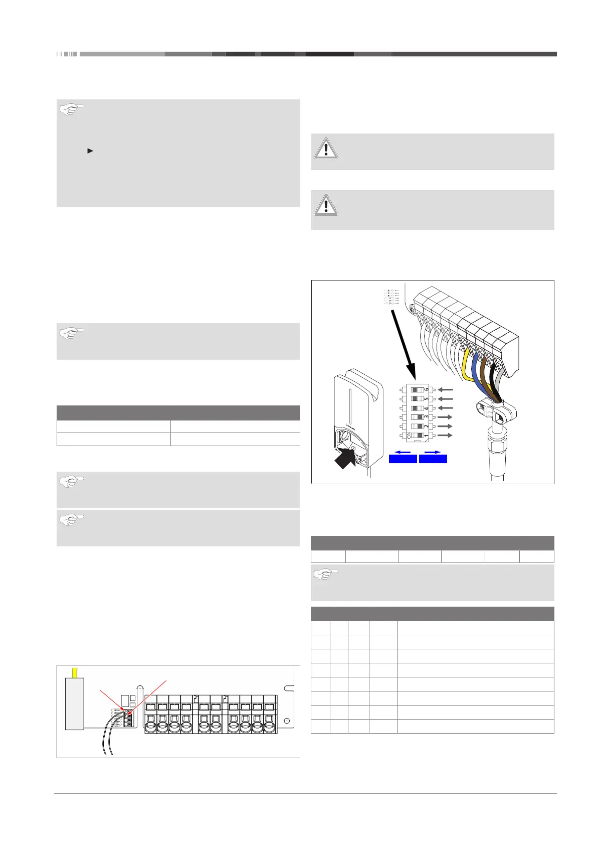
8.6 Active power increase
Fig.9
The active power control as per the rules of VDE AR-4100
should be connected as follows:
The two cables from the ripple control receiver or the floating
contact must be connected to this connector in positions 3 and
4 (see Fig. 9). The two cables can be assigned to pos. 3 and 4 in
any order (sequence). (max. cable cross section 1.5mm²).
WARNING
No voltage should be applied between terminals 3 and
4.
8.7 DIP switch settings
DANGER
High voltages.
u
Danger of fatal electric shock.
u
Ensure safe isolation from the power supply.
DIP switches determine the maximum current. The current can
be adjusted in 1A increments using the Charger Setup app up
to the maximum value that is configured by the DIP switches.
Fig.10
DIP switch left/ON = 1
DIP switch right/OFF = 0
DIP-switch factory setting:
D1 D2 D3 D4 D5 D6
Off Off Off On On On
NOTE
Changes to the DIP switch settings become active after
restarting the charging station.
D1 D2 D3 [A] Description
0 0 0 32
Factory settings
0 0 1 10
0 1 0 13
0 1 1 16
1 0 0 20
1 0 1 25
1 1 0 8
1 1 1 0
Demo mode: charging not possible