Operation | 14
5111232C OI-II Webasto Next_EN 17 / 23
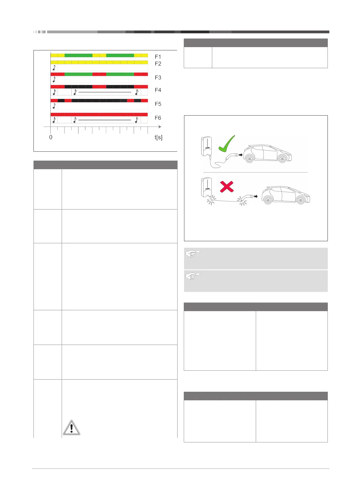
14.2.2 LED fault list
Fig.23
Fault list Description
F1 LED lights up green, there is additionally a yellow
pulse:
The charging station has become hot and charges
the vehicle with reduced power. After a cool-
down phase the charging station continues the
normal charging cycle.
F2 LED is yellow and an acoustic signal sounds for
0.5s:
Overtemperature. The charging function has been
interrupted and after a cool-down phase the char-
ging station continues the normal charging cycle.
F3 LED lights up green, there is additionally a red
pulse and an acoustic signal sounds for 0.5s:
There is a fault in the power connection to the
charging station, phase monitoring is active, the
power supply is outside the valid range of 200V
to 260V.
u
A qualified electrician should check the phase
sequence (clockwise phase sequence required),
network frequency, DIP switch setting and
protective conductor resistance.
F4 LED pulses red for 1 s at 2 s intervals and an
acoustic signal sounds for 0.5s, and then for 5s
following a pause of 1s:
There is a fault in the vehicle.
u
Re-connect the vehicle.
F5 LED pulses red for 0.5s at 0.5s and 3s intervals.
An acoustic signal sounds for 0.5s:
There is an internal fault with an extra-low voltage
(e.g. 12V).
u
Checking by an authorised electrician.
F6 LED is red and an acoustic signal sounds for 0.5s.
Then, after a pause of 1s, the acoustic signal
sounds for 5s:
There is a problem in the voltage or system monit-
oring.
u
Checking by an authorised electrician.
Danger of fatal electric shock.
Fault list Description
Switch off and secure the power supply to the
charging station. Only then unplug the cable from
the vehicle.
Table4: Fault indicators and troubleshooting
14.3 Start charging
In what follows, "Free charging enabled" describes the beha-
viour specified during installation. For "Free charging disabled",
see the information from chapter14.5, "Scan & Charge locking
function" on page 18.
Fig.24
NOTE
Always take into account the vehicle requirements be-
fore charging a vehicle.
NOTE
Park the vehicle for charging such as to avoid strain in
the charging cable. See Fig. 24
Action Description
u
Connect the charging
coupling to the vehicle.
Charging station performs sys-
tem and connection tests.
At the start of charging, the
LED strip which was initially
green starts to pulse blue. If
the vehicle is not ready for
charging (e.g. the battery is
full), a blue chase light runs up
and down.
14.4 Stop charging
The vehicle has stopped the charging cycle automatically:
Action Description
u
Unlock the car if necessary.
u
Unplug the charging coup-
ling from the vehicle.
u
Lock charging coupling in
the holder of the charging
station.
LED: Blue chase light running
up and down. Vehicle is con-
nected, not charging.