8 | Installation and electrical connection
10 / 23 5111232C OI-II Webasto Next_EN
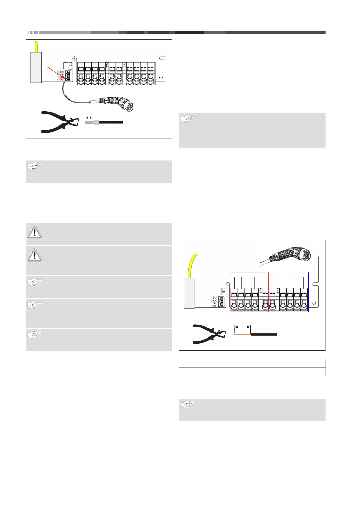
Fig.7
1. Connect the black/white control cable (CP) with a wire end
ferrule to the terminal (contact 1).
NOTE
Push the white spring contact of the connection on the
right down while inserting the control cable fully.
2. Perform a tension test to make sure that the cable is
clamped properly and fully.
8.3.2 Replace the charging cable
Charging cables are subject to wear and can be damaged, e.g.
by being driven over; in this case, replacement is necessary.
WARNING
The charging cable must only be replaced by a qualified
electrician.
DANGER
Danger of fatal electric shock.
u
Switch off and secure the power supply to the char-
ging station.
NOTE
Only use genuine Webasto parts of the same power
level.
NOTE
The charging cable may be replaced a maximum of
four times during the service lifetime of the Webasto
Next.
NOTE
If you require spare parts, please contact your installer
or dealer.
Procedure for replacing the charging cable:
1. Disconnect the power supply and vehicle charging line.
2. Remove the cover of the connection area in the wall box.
3. Disconnect the terminals and threaded cable connections
of the charging cable.
4. Remove the strain relief clamp and guide the damaged
charging cable downwards out of the wall box.
5. Install the new charging cable as described in
chapter8.3.1, "Connecting the charging cable" on page 9
(use only original Webasto replacement part).
6. Close the cover of the connection area in the wall box.
7. Carry out a new start-up as described in chapter8.8, "Initial
start-up" on page 12.
8.4 Electrical connection:
1. Check and make sure that the lead is tension-free and
measures have been taken to secure against being
switched on.
2. Check and comply with all the requirements necessary for
the connection and mentioned previously in these instruc-
tions.
3. Take the cable gland grommets from the supplied material.
4. Slide the cable bushing over the lead.
NOTE
Ensure that the insertion aid for the grommet is on the
back of the charging station when in the final installed
state, however, do not position it in the housing lead-
through yet.
5. If a data line is also to be connected, use the second sup-
plied cable gland grommet and repeat the above-men-
tioned step.
6. Remove the sheathing of the lead.
7. If a rigid lead is used, bend the individual wires paying at-
tention to the minimum bend radiuses so that it is possible
to connect them to the terminals without significant mech-
anical stress.
8. If a rigid lead is used, bend the individual wires paying at-
tention to the minimum bend radiuses so that it is possible
to connect them to the terminals without significant mech-
anical stress.
L3 L2 L1 N PE PE N L1 L2 L3
18 mm
L3/IN L2/IN L1/IN N/IN PE PE N/OUT L1/OUT L2/OUT L3/OUT
IN OUT
230 - 400 VAC
Fig.8
IN
Power cable connections
OUT
Charging cable connections
1. Using the slot-head screwdriver (3.5 mm), connect the indi-
vidual cable ends according to the specification in the illus-
tration (Fig. 8) on the left terminal block with the "IN" label.
NOTE
Make sure to connect them using the correct connec-
tion sequence for a right rotating field.
2. To do this, insert the screwdriver in the designated upper
opening of the spring relief for the terminal block and open
the clamping spring.
3. Now insert the individual wire into the designated connec-
tion opening of the terminal block (lower opening).