Installation and electrical connection | 8
5111232C OI-II Webasto Next_EN 9 / 23
1. Take into account the mounting position at the installation
location. See Fig. 20
2. Remove the drill template from the packaging at the per-
foration.
3. Mark the four positions of the drill holes at the installation
location using the drill template. See Fig. 19 and Fig. 20.
4. Drill 4 holes of Ø 8mm in the marked positions.
NOTE
The central hole (1) should be used for the building wir-
ing system. The hole (2) shown on the left must be used
if the LAN cable is used. See also Fig. 20.
5. Position the bracket over the upper holes and mount using
2 wall plugs and 2 screws, 6x70mm, T25.
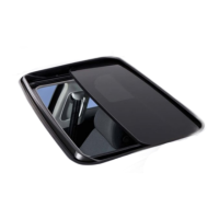
6. Remove the lower cover from the connection area of the
charging station.
Fig.5
1. Remove the spiral antikink protection from the connection
area of the charging station and place it with the other
supplied material.
2. For surface mounting, make a recess for routing the lead
on the back of the charging station using the designated
lateral predeterminedbreakingpoints (if necessary deburr
the edge of the break using a round file).
3. Insert the lead through the designated lead-through and fit
the charging station on the previously mounted bracket.
4. Mount the charging station using 2 screws, 6x90mm,
T25 using the mounting holes in the lower connection
area. Do not exceed the max. torque of 6Nm (Newton
metres).
8.3.1 Connecting the charging cable
1. Push the spiral antikink protection with the threadless
opening forward over the supplied charging cable.
2. Guide the charging cables through the previously pre-as-
sembled sealing clip.
NOTE
Ensure correct fit of the previously pre-assembled rub-
ber seals in the sealing clip.
3. Push the charging cable at least 10mm beyond the upper
edge of the clamping area of the strain relief clamp.
4. Turn the antikink protection spiral several turns onto the
sealing clip.
NOTE
Do not tighten yet.
Fig.6
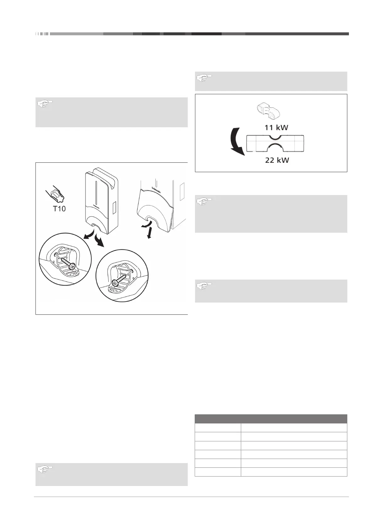
5. Screw in the supplied strain relief clamp in the correct posi-
tion on the charging cable.
NOTE
The strain relief clamp has two position options for
charging cable versions 11kW and 22kW.
Ensure that the “11 kW installed” label for an 11 kW
charging cable is visible.
6. Fit the strain relief clamp in the correct mounting position
using the supplied self-tapping Torx screws (6.5x25mm)
and tighten to 5.5Nm. (Attention: Do not overtighten
screws).
7. The strain relief clamp must be flush when securely
screwed in.
NOTE
Perform a tension test on the charging cable to make
sure that the cable cannot move.
8. Screw the antikink protection spiral onto the sealing clip
with a torque of 4Nm.
9. Using the slot-head screwdriver (3.5 mm), connect the indi-
vidual cable ends according to the specification in the illus-
tration (Fig. 8) on the right terminal block with the "OUT"
label.
10. To do this, insert the screwdriver in the designated upper
opening of the spring relief for the terminal block and open
the clamping spring.
11. Now insert the individual wire into the designated connec-
tion opening of the terminal block (lower opening).
12. Then pull the screwdriver out again and perform a tension
test to make sure that the individual wires are clamped
properly and fully.
Charging cable Description
Blue N
Brown L1
Black L2
Grey L3
Yellow-green PE
Black-white Control cable (CP)