6 | Installation and electrical connection
12 / 37 5111967A OI-II Webasto Unite
6.5 Using the cable glands
Fig.16
Pos. Description
1
AC mains cable gland
2
AC mains cable
3
Wrench
Fig.17
Pos. Description
1
Data cable gland
2
Data cable
3
Wrench
Proceed as follows:
1. Insert the cables (2) into the unit.
2. Tighten the cable glands (1) using the wrench(3)
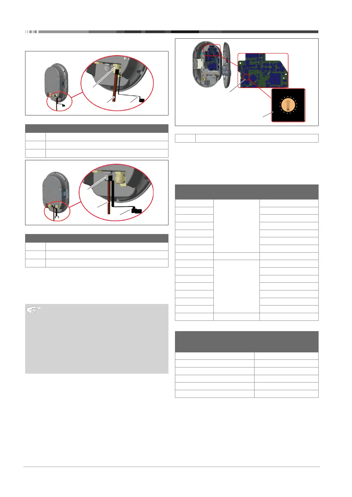
6.6 Adjusting the current limiter
NOTE
DIP-switch settings
DIP-switch settings are optional. All settings can be
changed by using the Setup App, or the web configura-
tion interface (see chapter8, "Unite Configuration Inter-
face" on page 20).
u
The most recent made setting will always be ap-
plied.
u
The current setting is shown in the web configura-
tion interface.
Fig.18
1
Rotary switch current limiter settings
The charging station has a current limiter (rotary switch) on its
mainboard. This switch sets the charging station’s current and
power limit. To change the settings, use a flathead screwdriver
to gently adjust the arrow in the centre of the rotary switch by
changing its position to the required-current rate. For rate de-
tails, see the table Current limiter positions.
Switch
position
Phase Current limit Value (22
kW)
0 1-phase 10 A
1 13 A
2 16 A
3 20 A
4 25 A
5 30 A
6 32 A
7 X X
8 3-phase 10 A
9 13 A
A 16 A
B 20 A
C 25 A
D 30 A
E 32 A
F X X
Required circuit breaker on AC mains
Charging Station
Current Limiter
Setting
C-Curve MCB
(miniature circuit
breaker)
10 A 13 A
13 A 16 A
16 A 20 A
20 A 25 A
25 A 32 A
30 A 40 A