6 | Installation and electrical connection
14 / 37 5111967A OI-II Webasto Unite
6.7.2 Data cable connection
Following data connection cables can be inserted through the
cable holes:
l External enable input cable
l Power optimizer measurement cable (external meter)
l Ethernet connection cables
l Load shedding triggering signal cable
l Shunt trip module control signal cable for welded relay
contact failure
Fig.23
Fig.24
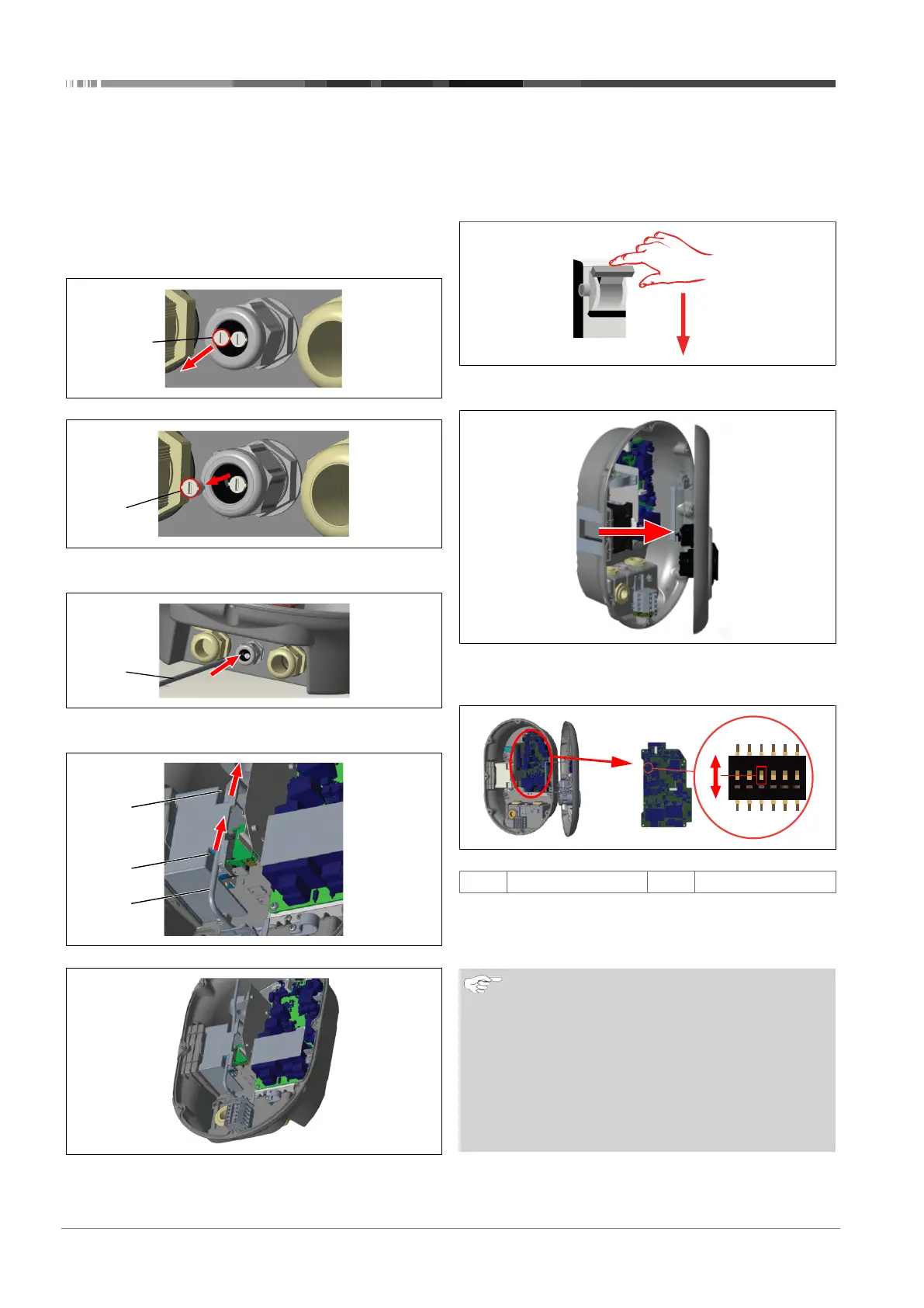
1. Remove the cork (1) from the cable gland.
Fig.25
2. Insert the cable (2) into the cable hole.
Fig.26
Fig.27
3. To connect the wires to the mainboard, check the applic-
able sections depending on the function(s) to be used.
6.7.3 Locked cable function
The cable will be locked and the socket model charging station
behaves like an attached cable model.
To activate this function:
Fig.28
1. Turn off the power to your charging station.
Fig.4
2. Open the product cover as described in the installation
manual.
Fig.30
ON
Enabled
OFF
Disabled
3. To enable the locked cable function, toggle DIP switch 3
into the ON position using a pointed spudger or a similar
plastic pointed tool. The DIP switch location is shown in the
above figure.
NOTE
DIP-switch settings
DIP-switch settings are optional. All settings can be
changed by using the Setup App, or the web configura-
tion interface (see chapter8, "Unite Configuration Inter-
face" on page 20).
u
The most recent made setting will always be ap-
plied.
u
The current setting is shown in the web configura-
tion interface.