EasyManuals Logo

WEG SSW07 Series User Manual

WEG SSW07 Series
11 pages
To Next Page IconTo Next Page
To Previous Page IconTo Previous Page
Page #6 background imageLoading...
Page #6 background image
6
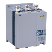
Control via 2-Wire Start/Stop (Remote Mode):
Figure 3 – Control via 2-Wire Start/Stop
Control Wiring:
Start/Stop switch is N.O. (normally open) and is wired as shown in Figure 3.
Parameters (Optional HMI):
1. Set P220 = 1 Always Remote
2. Set P230 = 1 Digital Inputs
3. Set P263 = 1 DI1 Enable/Disable
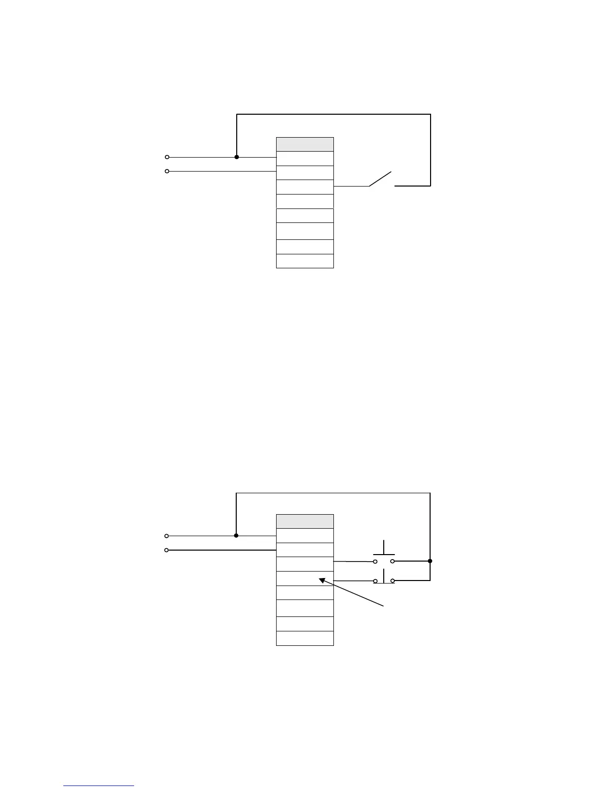
Control via 3-Wire Start/Stop (Remote Mode):
Terminal
A1
A2
DI1
DI2
DI3
13
14/23
24
Figure 4 – Control via 3-Wire Start/Stop
Control Wiring: “Start” and “Stop” are momentary push button switches and are connected as shown in Figure 4. “Start”
is a N.O. (normally open) contact and “Stop” is a N.C. (normally closed) contact.
Terminal
A1
A2
DI1
DI2
DI3
13
14/23
24
Start/Stop
Line
Neutral
Control
Start
Stop
Note:
DI2 will need to be
programmed for 3-Wire
control.
Line
Neutral
Control

Questions and Answers:

Question and Answer IconNeed help?

Do you have a question about the WEG SSW07 Series and is the answer not in the manual?

WEG SSW07 Series Specifications

General IconGeneral
Control TypeVoltage Ramp (VR), Current Limit (CL)
Starting MethodSoft Start
Number of Starts per HourUp to 10
Frequency50/60 Hz
Protection DegreeIP20
ProtectionPhase Loss
Operating Temperature-10 to 50 °C
CommunicationRS485 Modbus RTU
Bypass ContactorOptional
HumidityUp to 95% non-condensing
AltitudeUp to 1000m
Voltage220-575 V
Input Voltage220-575 V
Storage Temperature-25 to 60 °C

Related product manuals