TECHNICIANS' manual 11 of 100
General safety features
The Technician must be aware of accident risks, safety devices
and the general safety rules set forth in EU directives and by
the legislation of the country where the machine is installed.
The Technician must know how all the machine's devices
work. They must also have fully read and understood this
Manual. Maintenance work must be performed by the Techni-
cian after the machine has been properly prepared. The tam-
pering or unauthorised replacement of one or more machine
components, the use of accessories which modify its use and
the use of materials other than those recommended in this
Manual, can cause accidents.
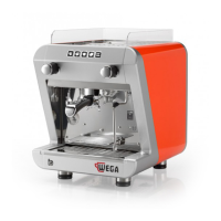
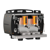
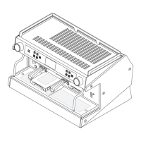
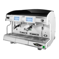
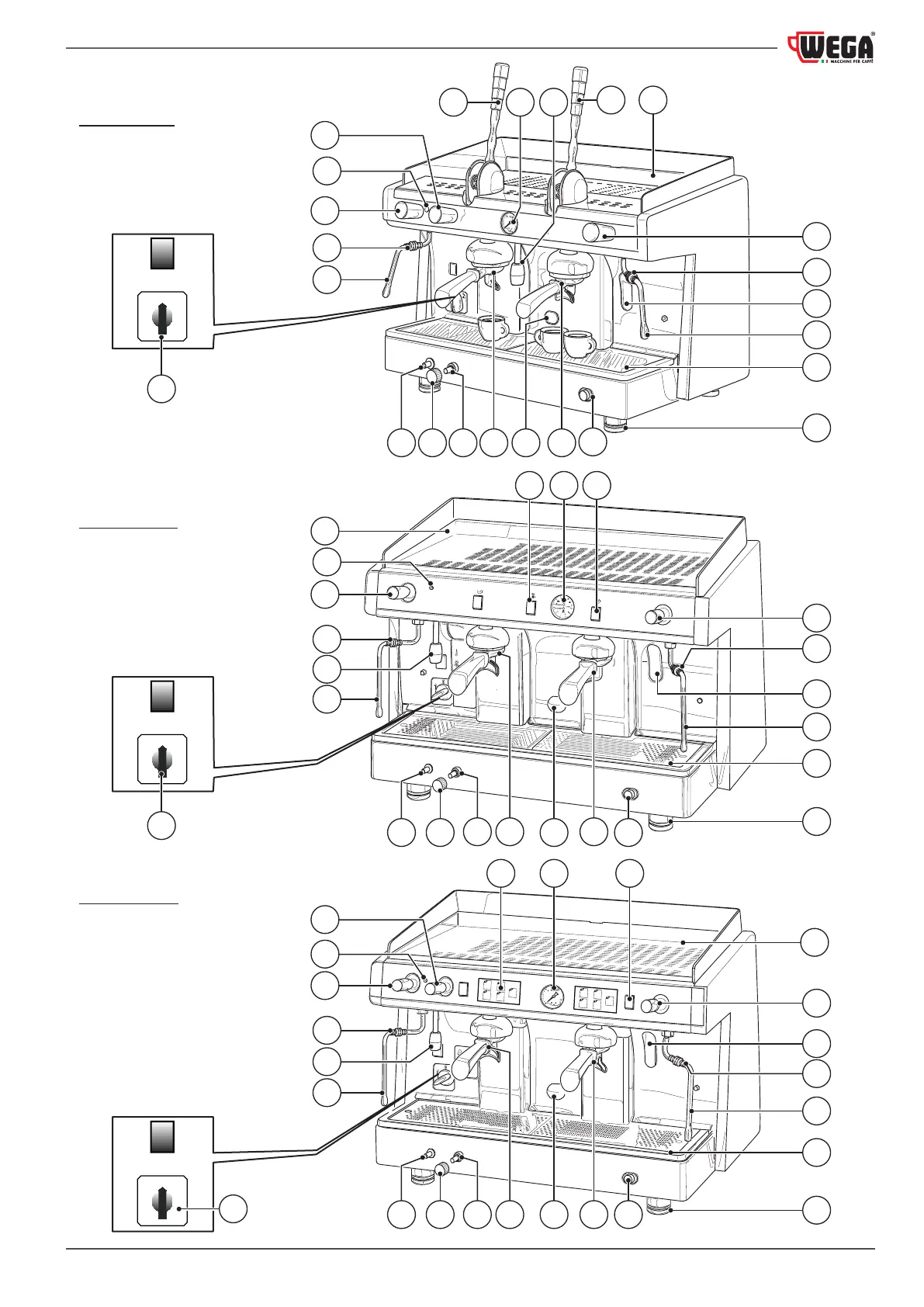
2.5 Machine diagram
1. Cup warmer shelf
2. Group lever
3. Heating unit water level window (in some versions, the
level window is replaced by a green indicator light)
4. Pressure gauge
5. Steam knob
6. Scald protection
7. Steam nozzle
8. 2-cuplterholder
9. Adjustable foot
10. Hot water nozzle
11. Gas burner inspection window (optional)
12. 1-cuplterholder
13. Gas safety (optional)
14. Gas adjustment (optional)
15. Gas ignition button (optional)
16. Cup holder grille
17. Power switch
18. Machine on indicator light
19. Hot water knob/button
20. Manual dispensing switch
21. Pushbutton panel
22. Heatingunitmanualwater-llingbutton
23. Cup warmer button
24. Blindlter
25. Presser
26. Cleaning brush
24
25
26
1 2
0
1 2
0
1 2
0
ALE version
EPU version
EVD version
1
2
3
6
2
6
6
3
5
5
5
17
3
7
7
7
9
9
16
16
16
9
4
419 20
20
21
812
12
12
11 22
22
22
14
14
14 11
111315
15
15
8
8
13
13
17
17
1
7
7
6
6
6
10
18
18
19
19
18
10
7
5
5
5
1
4 10