TECHNICIANS' manual 53 of 100
12. WIRING DIAGRAMS
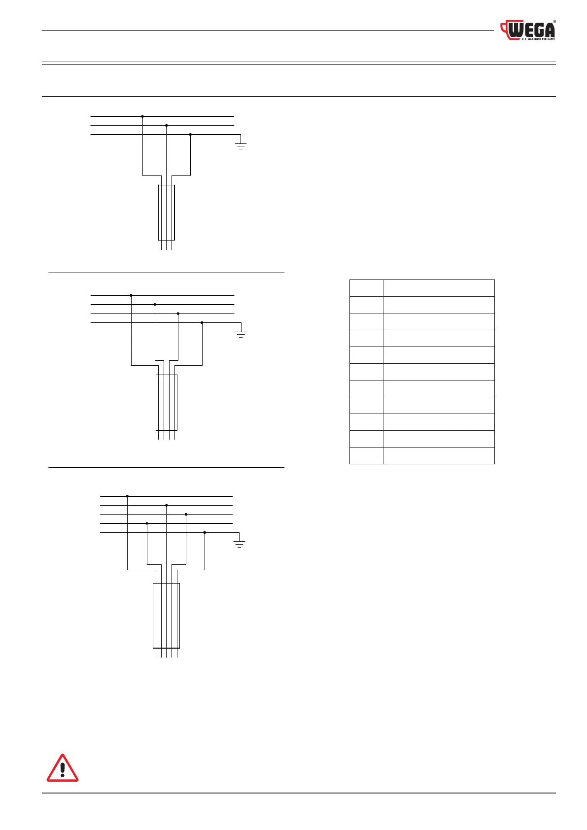
12.1 ELECTRIC MAINS connection
R Phase
S Phase
T Phase
N Neutral
Earth
BU Blue
CAB
Power cable
GY Grey
GNYE Yellow-green
BN Brown
BK Black
R
N
S
N
T
R
S
R
T
CAB
CAB
CAB
BN
BU
GNYE
*BK
*BN
BN GNYEBK BU
BU BK GY
BN
GNYE
3-CONDUCTOR CABLE (Phase+Neutral+Earth)
4-CONDUCTOR CABLE (3 Phase+Earth)
5-CONDUCTOR CABLE (3 Phase+Neutral+Earth)
(*) For Brazil
To correctly connect the machine to the electric mains, please refer to the information provided on the
nameplate (see the example in paragraph 2.7).