TECHNICIANS' manual 43 of 100
7.3.2 Maintenance after a short period
of machine inactivity
“Short period of machine inactivity” refers to a period of time
exceeding one working week.
If the machine is switched back on after this period, all the
water inside the hydraulic circuits must be replaced as indi-
cated in para. 6.7.
Furthermore, all periodic maintenance operations must be
carried out, see the previous paragraph.
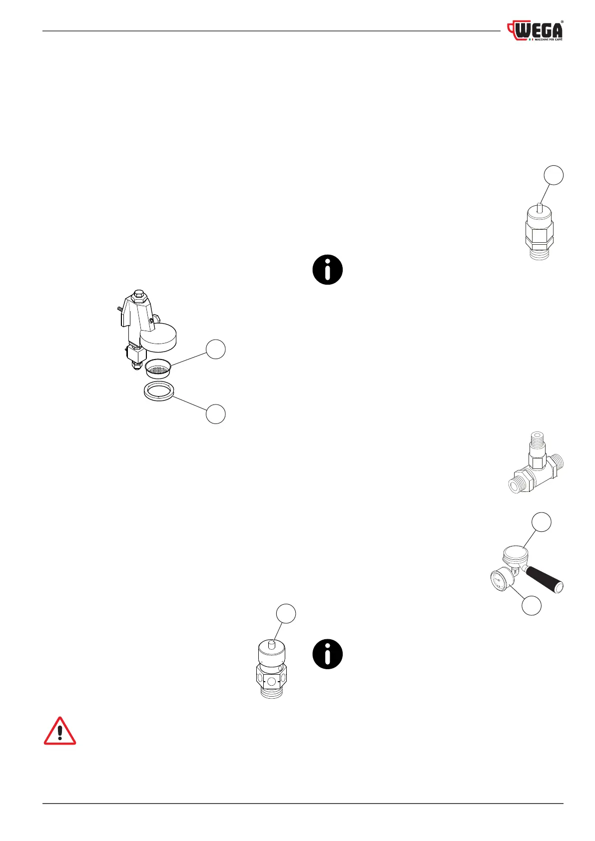
7.3.3 Dispensing group maintenance
Replace the dispensing group's shower screen (1) and group
gasket (2) on a quarterly basis (we recommend only using
original spare parts).
1
2
7.3.4 SAFETY VALVE check
The pressure relief valve is one of the main components for
machine safety. Therefore, it is important to carry out the fol-
lowing checks:
First check:
• Remove the machine's upper grille.
• Use pliers to pull the valve pin (6) upwards.
• If the pin will not budge, it probably means that the valve
is encrusted with limestone and must be replaced.
Second check:
• Turn the machine off.
• Close off the pressure switch contacts.
• Turn the machine back on and wait for the
pressure in the heating unit to rise.
• Check that the valve is working correctly at
the maximum pressure of 0.19 bar (1.9 bar).
If any malfunctions are detected, the valve must
be replaced. Only use the Manufacturer's original
Safety Valves.
6
7.3.5 NEGATIVE PRESSURE VALVE check
First check:
• Remove the machine's upper grille.
• Use pliers to push the valve pin (5) downwards.
• If the pin will not budge, it probably means that the valve
is encrusted with limestone and must be replaced.
Second check:
• Turn the machine off.
• Open the steam valves and release all the pres-
sure from inside the heating unit.
• Turn the machine back on and check that the
valve is closing normally.
If any malfunctions are detected, the
valve must be replaced.
7.3.6 NON-RETURN DRAIN VALVE check
The non-return drain valve is an important component for
the correct operation of the machine. Perform the check as
follows:
• Activate the dispensing groups for about 30 seconds.
• Attach a lter holder (7) with a pressure
gauge (available on request) to the dis-
pensing group.
• Activate the dispensing group, and use the
pressure gauge (8) to monitor the pressure
as it increases up to 0.8-0.9 MPa (8-9 bar).
• Check that the pressure is increasing
due to the heated water expanding
until it reaches approximately 1.2 MPa
(12 bar): when this value is reached,
it conrms that the valve is working
correctly and the seals and solenoid
valves are tight.
• Stop dispensing.
• Repeat the check on the other dispens-
ing groups.
If any malfunctions are detected, the valve must
be replaced.
5
7
8