10
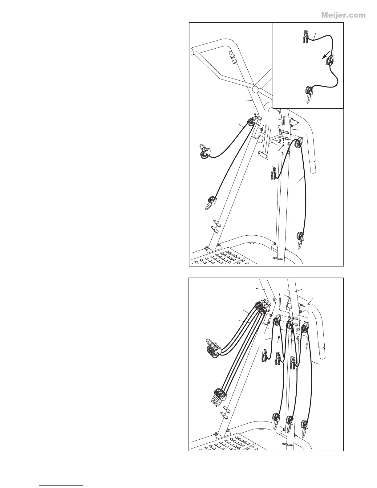
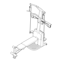
9. See the inset drawing. Identify a 45-lb.
Resistance Cord (34), which is marked on each
end with a “45.” Orient the 45-lb. Resistance
Cord so that the center pulley bracket
slopes downward as shown.
Attach the center pulley bracket on the 45-lb.
Resistance Cord (34) to the center hole in the
indicated bracket on the Right Frame (6) with
an M6 x 66mm Bolt (39) and an M6 Locknut
(37).
Attach the other 45-lb. Resistance Cord (34)
to the Left Frame (7) in the same way.
9
10
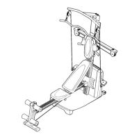
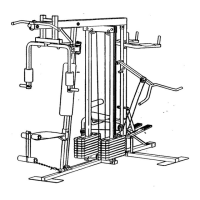
10. Identify a 25-lb. Resistance Cord (36) and a 35-
lb. Resistance Cord (35), which are marked on
the ends. Orient the Resistance Cords so
that the center pulley brackets slope down-
ward.
Attach the center pulley bracket on the 25-lb.
Resistance Cord (36) to the inner hole in the
indicated bracket on the Right Frame (6) with
an M6 x 66mm Bolt (39) and an M6 Locknut
(37).
Attach the center pulley bracket on the 35-lb.
Resistance Cord (35) to the outer hole in the
indicated bracket on the Right Frame (6) with
an M6 x 66mm Bolt (39) and an M6 Locknut
(37).
Attach the other 25-lb. Resistance Cord (36)
and the other 35-lb. Resistance Cord (35) to
the Left Frame (7) in the same way.
34
Center pulley
bracket slopes
downward
34
34
7
35
7
6
35
37
37
37
39
6
36
36
39
39