1066540000/00/02.09
15
5.8 Encoding
NOTICE
Leaving the product connectors uncoded results
in lack of interchanging protection. All connectors
will be identically encoded.
• Create connector coding plan prior to first
mating and encode connectors accordingly.
• Perform encoding procedure for each new
module.
The product housing is equipped with an automatic
encoding.
This connector interchanging protection is initially
encoded upon shipping and can be individually
adjusted.
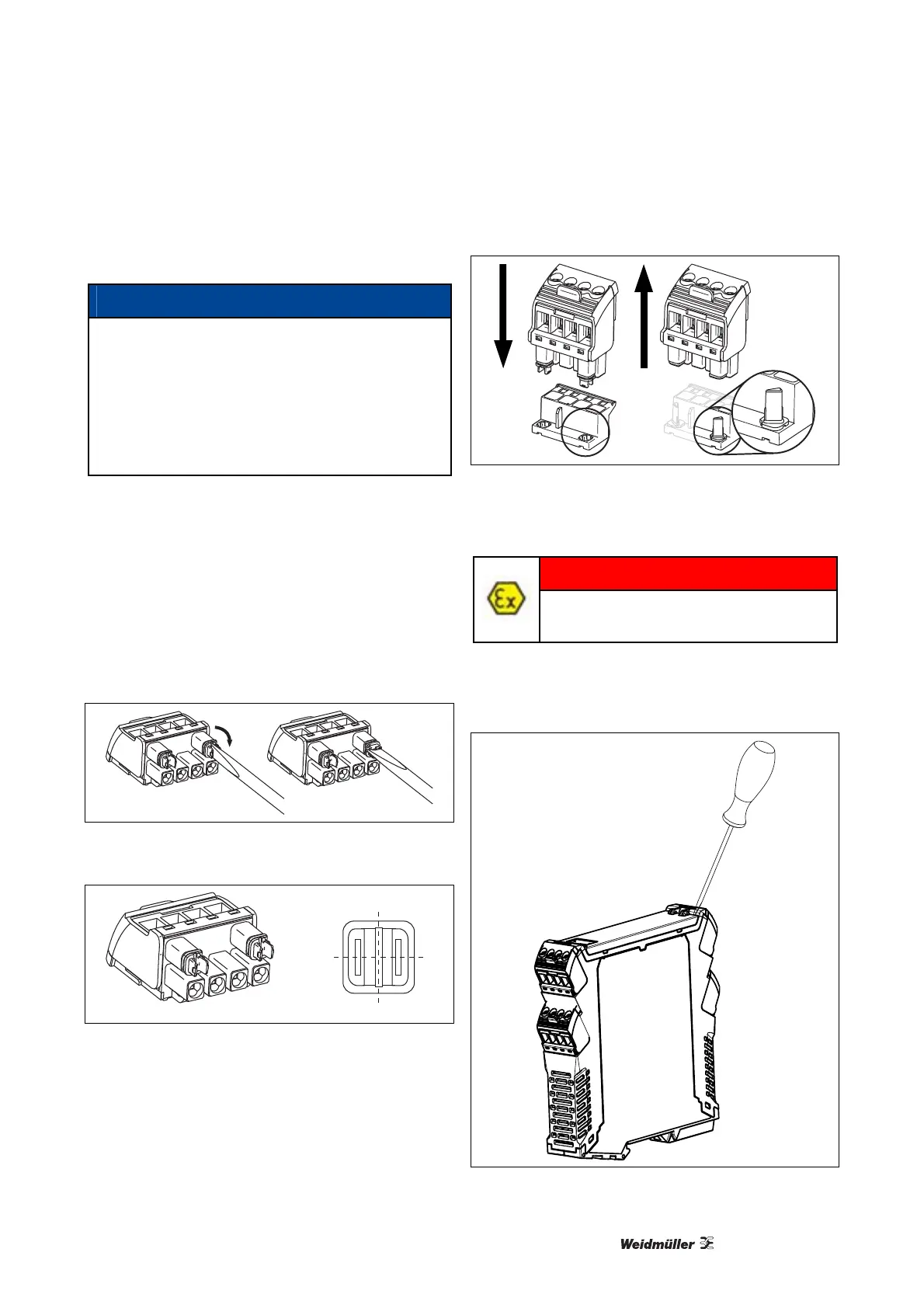
1 Use screw driver to turn adjusting dial of
connector clockwise.
Either dial has 4 encoding positions, resulting in
4² = 16 possible positions.
Connector is encoded.
Illustration 5-5: Encoding Connector
0
1
2
3
Illustration 5-6: Encoding Positions
2 Plug encoded connector onto pin header.
Encoding element is transferred from connector to
pin header.
Encoding element remains in the pin header
housing.
Illustration 5-7: Transfer Encoding Element
5.9 Configuration
DANGER
Configuration must be performed in a
safe area!
Configuration is performed via a connector located
behind the front flap.
1 Open the front flap, as shown in the illustration:
Illustration 5-8: Opening Front Flap